Electronics, Schematics, Processor Details, and Working Code Examples
Steve Luce
Revision 2.4 17 June 2016
Update on the use of a single voltage source to drive the ADC chip and the ADC reference input
How to actually make these things work...
T H E P U R P O S E O F T H I S W E B P A P E R
This
paper is about the amateur electronics person and non-electronics
professionals and their quest to actually analyze and display a 24 bit
presentation of analog data. This web paper discusses and offers a number of methods to apply a 24 bit ADC (Analog to Digital Converter) to the real world of analog data. This paper explains the conversion of the analog information into very high resolution digital data. The paper below includes methods of moving the real world analog data into a standard digital computer. The computer can be a Windows 7 operating system PC, a Linux OS PC, a Mac OS PC or a single board Android or Raspberry Pi system. The point of this paper is to show the relative simplicity of each of these steps meaning that it is fairly simple, with todays incredible technology, to read analog information into a standard computer in digital form to extreme resolution and to read analog signals down to billionths of a volt - that is billionths with a B - also known as nanovolts! By the way, Picoamperes and femtoamperes (quadrillionths of an amp - 800 electrons/sec) are possible to measure but with extreme care in high gain circuit design, component selection, EMI shielding, temperature control, and board trace layout. This paper uses the LTC2440 as a specific example of the use of a 24 bit ADC but this discussion below applies to any high resolution ADC, provided that the investigator can develop the code to drive the ADC. I have also used the Arduino Uno as an example of a microprocessor but any microprocessor can be used with the same considerations mentioned with the LTC2440, - the user must have the ability to code the microprocessor control lines to be used. Although I mention the Linear Technologies products often, I am in no way associated with Linear technologies. But they are the only commercial technology group of which I am aware, that has specifically developed an Arduino/microprocessor language link (Linduino) to help amateurs work with the LTC ADCs - thank you LTC! LTC also has an excellent and well documented product line. I have chosen to task a dedicated microprocessor with the busy work of collecting the analog information and controlling the ADC timing and then sending the ADC digital data to a serial out Com/USB port on the microprocessor. All of this work can be done inside a high performance, high cost PC but it seems to be a waist of computer power to control complex and high speed menial tasks when a $25 processor can manage most of the data collection and analog to digital control processes - it becomes a kind of delegation issue. The task of managing the analog data collection also protects the expensive, high performance computer from potentially dangerous analog data collection wiring errors. Imagine reading analog data coming from a 200 volt device and making a wiring error, sending 200 volts into an expensive PC comport! Steve |
I found an amazing lack of specific information, at the amateur level, in both LTC2440 coding and LTC2440 schematics available on the net (this applies to all other high performance ADCs manufacturers) until the much needed Linduino language aid was developed by LTC. Even getting the LTC2440 started was a challenge. My purpose with this website is to create a general open source page with no hidden agendas - just free information. This website is here to help and promote the amateur and professional knowledge of the application and use of the 24 bit ADC.
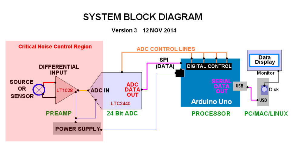
For those of you who think as I do - visually - here is a greatly simplified block diagram of the analog to digital conversion process discussed in this paper - remember this is a 24 bit ADC system capable of nanovolt measurements and resolution of data to one part in one million allowing for 4 bits of noise. See the noise section below for specifics on limitations of background noise. The "preprocess" or ADC data-in preparation area of the diagram (left of the blue vertical line) is, most importantly, a buffer/amplifier between the analog sensor and the ADC input.

Much of my information is greatly simplified and intended to both teach
and to encourage the use of 24 bit ADCs. This discussion is intended
for people from age 12 new to electronics and science in general to senior scientists not
quite sure of the detailed "state of the art" electronics available in
the process of placing real world data in a computer for analysis. The
"preprocess of analog data" shown as the second step from the right
depends on the data device. But it has been my experience that some
kind of buffer wired op amp is critical for most analog sensors - most
sensors do not do well if fed directly into a 24 bit ADC. Much of
this paper's content can be duplicated, built, and coded in a matter of
days as you will see later. The basic cost was another goal of mine and
it is my belief that this project parts cost, as illustrated in this
diagram, can be built for less than $100 US including the Arduino Uno processor and not including the PC and monitor. A number of very knowledgeable professionals have helped in the assembly of this page including John Beale, Ted Channel, and Mark of Australia. Mark is working on the use of the LTC2440 in the analysis and health of the human eye with the goal of improving modern medical systems usable in non-medical and remote environments. Ted is working on low cost seismographs used worldwide as teaching tools. I have also received guidance from a very helpful senior satellite design engineer especially on the 24 bit volt meter design. | Much of the front
end of the design has been with his suggestions and and ideas on low
noise component use. The 24 bit volt meter noise would not be at the 50
nanovolt level without his help. A point to consider - a 24 bit ADC will give the user a thousand times the information that 16 bit ADC can provide! A new person has made contributions to this website. I am pleased to say that Stefan Schäfer an electrical engineer with Heidelberg University, Institute of Environmental Physics has been helping with coding and helping in our continuous drive to reduce noise in these circuits. Stefan has successfully produced a modest system in his lab that appears to be showing 1 uV accuracy with a very low noise levels at that voltage. Stefan is working on the development of an ultra high gain sensor that would be much like a beam current measurement in a particle accelerator. Stefan's amateur radio call sign is DK7FC.This is what open source is all about!!!!! Anyone interested in contributing to this page with other applications or new thoughts and detail to add to this page is welcome - please send me an email with your thoughts by visiting the Contact me section of this website - ALL contributions and comments are welcome! Thank you for visiting this page. Much of what is said and documented on these pages applies to the entire LTC24XX family of ADCs. Some of the code below is directly interchangeable with other Linear Technology 24 bit ADC products. |
| TABLE OF CONTENTS |
This is an essential block diagram that provides a visual summary of the basic LTC2440 application.
This section has a series of very simple startup schematics. Most people with some experience building electronic breadboard circuits can use these schematics to construct a working 24 bit ADC system in an afternoon.This is a simple single end 3 wire sensor schematic - very easy to construct.This is a discussion of the differential amplifier and its use with the 24 bit ADC. It is my opinion that the differential amplifier is the best possible way to achieve nanovolt range measurements.This is a full schematic of a working 24 bit volt meter. The point of this schematic is that the 24 bit ADC and preamp can measure ANY voltage to extreme resolution. 24 bits enables the measurement of a voltage to 5 and 6 places depending on the source stability. It was my experience that 24 bits is much like using a microscope when all I had ever used was a magnifying glass. The extreme detail of an analog signal can be fully realized at 24 bits. The present noise level of this design is about 50 nanovolts and getting lower by the week. This design is a cooperative effort, I could not have attained the low noise levels on my own - this is the point of open source shared efforts.I have completely abandoned any form of switcher circuitry in my system. Low quality "switcher/buck-boost" circuits are very dirty with high frewuency noise. And this high frequency noise is not easily supressed with capcitors. I also need to show more detail on the linear power supply I am now using. I have borrowed from the high performance audio people who were the first to understand the importance of ultra low noise DC power supplies in high gain circuits. This circuitry will be shown on a separate page because of the complexity of the circuits and the need for several different approaches. ANY suggestions here would be greatly appreciated.This is a quick example of the measurement of a microvolt signal and the amazing detail of 24 bits!There are only two elements of a high resolution view of analog data. The first is the signal size, and the second is the noise of the analog signal environment. I have spent quite a lot of time lowering the noise of the circuits shown on this website. I am now confident the LTC24XX family of ADCs can measure into the low nanovolt region with extreme care in building the low noise circuits to keep circuit noise at a minimum. Signals as low as 80 nanovolts can be resolved - that is 80 billionths of a volt - billion with a B!
CODE SETUP ON THE LTC24XX FAMILY ADC
It is critical that a microprocessor control the ADC. Yes, a general computer can do the work but it seems much more efficient to let a microprocessor do the "busy work" and let the main computer simply process and display the data.INTRODUCTION TO ARDUINO/LTC2440 CODE
I selected the Arduino simply because is small, cheap, and fairly well documented. Any good processor can be used.This is the heart of the successful operation of an LTC 24 bit ADC - ADC control code. This is the code that operates the processor and lets the processor output serial data to a main computer. This code will work with Windows based systems, Mac OS, and LINUX. The Arduino processor is commanded by this code to control all ADC timing and output controls and ultimately delivers a serial data string and a line return. It then becomes the job of the main computer to process the serial data and to display the information as data and/or a graphic display.
Beale Code Listing This is a working code listing for the LTC2440 developed by John Beale but limited to sample rates of 7 or 880 samples per second.
Getting Linduino into the Arduino library This is the process of downloading the LTC Linduino library language set and installing it as an Arduino Library.
Schäfer Code Listing and the LTC2440 This is a working code listing for the LTC2440 which uses the Linear Technologies Arduino interface code to, among other things, to control the sample per second rate. This code has full control of the sample per second rate from 7 samples per second to 4000 samples per second.
MOVING DATA FROM THE ARDUINO BOARD TO A COMPUTER
The Windows OS is a choice I have made so I have used a "shell" program called "processing.org" to access a serial device output such as the Arduino Uno board. I can read the serial data into my PC, hold it in my PC, send it to disk, process the data, and display the data on my PC. Python is another well known method to display data on a UNIX based computer. It is also very possible to use the new single board processors such as the android family of boards, or the Raspberry Pi. This section is on the process of really doing something significant in a computer, with serial device generated data. This is about bridging the gap (chasm) between real world analog data and pure digital computers.MULTIPLE SENSORS AND REMOTE SENSORS
I have experimented with both wireless and multiplexing (multiple sensor measurements) . Multiplexing is simply a matter of adding a 8 or 16 channel multiplex board and controlling the "data out" stream with the Arduino board. It is also possible to multiplex with some of the LTC multi-channel ADCs. But I have found the LTC 8 channel ADCs a bit complex to work with - I have enough trouble dealing with the data stream from a single sensor.ELECTRONIC COMPONENTS - Where to buy them..."parts is parts" ...sometimes...
We all face the issue of where to buy a critical component and how to find authentic top quality quality at the best possible price. This is my opinion with a few suggestions - a list of places I buy parts and why this list is necessary. This is also my thinking on quality vs. price in the construction of high performance prototype circuits.CONTACT ME (Direct to new window, "contact me" page)
If you have questions or corrections to suggest, please contact me at this link.
This is a list of papers on op amps, ADCs, etc., and technical data sheets from various component manufacturers.
| INTRODUCTION |
BACKGROUND
The purpose of this paper is to allow a person to start with a few basic components of modest cost and build a high performace 24 bit resolution readout of an analog voltage. With a basic circuit built, a person can input an analog or sensor voltage, such as temperature, at one end of the circuit and see a 24 bit (high resolution) digital readout on a computer screen. It is easier than it sounds but it does take a while - this is not an over night project but still possible with electronic and coding knowledge or a friend willing to help with such thngs. Since an Arduino processor is used to process the data, there is almost no risk to the main computer.
The most important point I hope to make on this website is the versatility of such a circuit and the amazing range of applications.
In my general review, I would like to emphasize the following system specifications, each point being significant in itself.
- The simplest example use of this circuit is a 6 to 7 place AC or DC volt meter.
- The circuit is especially well suited to analog sensors of any type that output some voltage proportional to a natural event such as air temperature, environment humidity, vibration, light levels, etc. There are numerous, low cost, devices which will measure such variables but this system can show measurable, repeatable changes of one part in 100,000 and better.
- The amplifier can be AC or DC with the addition of a single capacitor.
- The sample rate can be any rate from 6 samples per second to 880 samples per second. The sample rate is set in the microprocessor coding and is very simple to adjust.
- The total cost of the ADC/amplifier is less than $75 (US) including the processor depending on the components and component grades selected.
- The maximum gain I have been able to use that will produce data readable over ambient noise (data 10x over noise) has been 20 bits or a gain of about one million. Gains of 21 and even 22 bits are possible but become increasingly difficult with respect to sample rate, cost, shielding complexity, temperature, and general component generated noise. Reading voltages in the high nanovolt range requires extreme component selection, special shielding, detailed attention to component layout, and high quality components at all stages.
- I have made extensive noise measurements which are of interest to some and not to others. But the essential point is the system is capable of measuring one part in one million with the one part ten times the noise level. I will show noise measurements later in this site.
- I will include examples of Arduino code I have developed on this site. Most of the code is experimental and not developed for good efficiency. Moderate speeds can be used but for anyone looking for extreme speeds, I would suggest a careful look at the code for items such as library calls, unnecessary loops, the total lack of error checking, etc. I would be very interested in hearing from anyone concerning code and especially methods to improve the code.
FROM THE BEGINNING
| Before we start the next section on analog to digital convrsion - Two very important definitions | ||
| Formal definition of an analog signal... An analog or analogue signal is any continuous signal for which the time varying feature (variable) of the signal is a representation of some other time varying quantity, i.e., analogous to another time varying signal. For example, in an analog audio signal, the instantaneous voltage of the signal varies continuously with the pressure of the sound waves. It differs from a digital signal, in which a continuous quantity is represented by a discrete function which can only take on one of a finite number of values. The term analog signal usually refers to electrical signals; however, mechanical, pneumatic, hydraulic, and other systems may also convey analog signals. | Formal definition of a digital signal... A digital signal is a physical signal that is a representation of a sequence of discrete values (a quantified discrete-time signal), for example of an arbitrary bit stream, or of a digitized (sampled and analog-to-digital converted) analog signal. The term digital signal can refer to either of the following:
| |
| Translation...an analog signal varies in value in no set step or change. Example: Temperature | Translation...a digital signal is a defined, strict, group of pulses. Example: Morse Code | |
IN FACT - WHAT IS AN ADC?
Describing an ADC can be so complex the actual use and value of an ADC can be lost in the detail. If you want to read about the detail of the ADC please read these pages which go into extreme detail. This description is nicely done and fairly easy to follow for a person new to ADCs - these links will open as a new window - you will not lose this MAIN ADC site if you take a quick look - just close the new window and you will be right back here. This is the way all hyper links work on this website: http://www.hardwaresecrets.com/article/317 This is a very nice and very technical description of an ADC: http://en.wikipedia.org/wiki/Analog-to-digital_converter The essential understanding of an ADC is more with the purpose than the internal workings. An ADC converts analog signals to digital. We live in an analog world - except for computers, there is nothing in our life and our world that is digital. Our vision, for example, is an analog process of sensing photons, understanding their structure, and then processing the information in our brains. Now what happens inside the working brain is extremely complex and could possibly be a digital process. Weather is all analog - temperature, humidity, wind speed, etc. The human mind simply works hard to interpret an analog world to survive. BLIND COMPUTERS Computers are ALL digital. Every circuit in a PC is digital. A computer can not, in any way, read analog information by itself. For the detailed computer people out there, I do understand that the sound card has an very limited analog input. But the analog sound input is very quickly converted to digital information using a small, modest, ADC inside the PC! A computer can not know what color its case is, it can not measure its height off a table, it simply is sensually blind to the world. Even data input into the computer from a disk or modem is in an all digital format. A computer is really just a dumb box inputting and processing digital alphanumeric characters very quickly, and displaying information on a screen in digital pixels. It may be a good thing computers can not tell us what they think of us. | So how do we get along with our digital friends? - with the ADC - of course! Actually we do not always get along with our digital friends but that is a different subject. The ADC is the bridge - the link - between the real world and the computer. An ADC is the single most important electronic component in or connected to the computer today if, the computer needs to understand or monitor the real world! The ADC creates the eyes, ears, nose, and even the sense of touch of the computer. All environmental sensors go through an ADC to let the computer to know what is happening in the real world. Yes, a computer can ask another computer what the temperature is in San Francisco but someplace in the chain of computers, there is an ADC at the beginning of the chain reading, and converting to digital-speak, the real world temperature in San Francisco. Even sub systems such as a robotic device must have ADCs on board to enable the robot to sense the world. Most smart phones have motion detector sensors and ADCs inside. THE 24 BIT ADC This website discusses a 24 bit ADC. A 24 bit ADC is a common 12 or 16 bit ADC on steroids. As an example, a 24 bit ADC can see or sense, a 1000 times more clearly than a 12 bit ADC can sense. If a science experiment measures temperature with a 12 bit ADC it can measure temperature to 3 places - 23.5 degrees C as an example where a 24 bit ADC can measure to 6 places or 23.4894 degrees C. So it is obvious both devices are important - you do not need to know your outside air temperature to 5 places but you might want to see minute location changes to measure the exact movement of a volcano about to erupt. It seems probable that reading the GPS location to 6 places of accuracy on Mount St. Helens could have saved lives. If 24 bit ADC sensor and location systems (which did not exist at the time) were used in early 1980, they would have seen the flank develop a large bulge and then explode. Knowing this bulge was developing, the side directed eruption probably would have been predicted and the down stream area would have been cleared. The good news is that his is how high performance ADC/GPS systems are being used today on many volcanoes around the world! | |
THE LTC2440 | ||
| This website discusses a particular 24 bit ADC made by Linear
Technologies called the LTC2440 and the general family of LTC ADCs
which are all very similar and generally interchangeable as far as
general code to control the LTCxxxx family is concerned. I think the essential point to make about a 24 bit ADC, after working with the LTC2400 and LTC2440 for three years, is the amazing voltage resolution or accuracy of a 24 bit measurement. A 24 bit ADC converts a analog voltage to a digital voltage and the "detail" - or the resolution is what makes the 24 bit ADC special. 24 bits is capable of resolving a voltage to one part in 2^24 or one part in 16777216 parts. This, said a different way, means a voltage can be accurate to .0000006 volts or 7 places or 600 nanovolts. But most noise in modern electronics is well above 600 nanovolts. In fact most typical quality circuits have about 5 microvolts of noise or 10 times the voltage resolution of a 24 bit ADC. The reality then says that 24 bits is really usable to 21 bits and more likely to 20 bits. This means that good data can be measured at 20 bits or one part in one million or to 6 places. Most of this website is based on 20 bits of usable resolution from a 24 bit ADC. | There
are a few very carefully designed 24 bit systems which can measure to
Picoamps (trillionths of an amp) but the engineering is very complex
because of environmental noise. Even Femtoamp measurements may be
possible but difficult - a quadrillionth of an amp! The good news is that there are many modern requirements for voltage measurements to 6 places or to a millionth of a volt. And there are many new applications where 10 millionths of a volt is the analog voltage of the source and this resolution allows us to see nature with a much stronger analog voltage microscope than ever before!!! As an example, today's astronomy can detect planets in other solar systems (in deep space) with the ability to measure and track data variations in the 5 microvolt range. Another example is the ability of modern medical systems to measure eye health when the electrical data of the measurement is to 5 to 10 millionths of a volt. Science is demanding accurate measurements to smaller and smaller voltages and the 24 bit ADC is part of the answer. The fluent and precision use of a 24 bit ADC is critical to modern science and to new discoveries including amateur contributions. The 24 bit ADC is now easily available to amateurs. This is the reason for the numerous referrals to 6 place voltage accuracy in this website. | |
| BLOCK DIAGRAM |
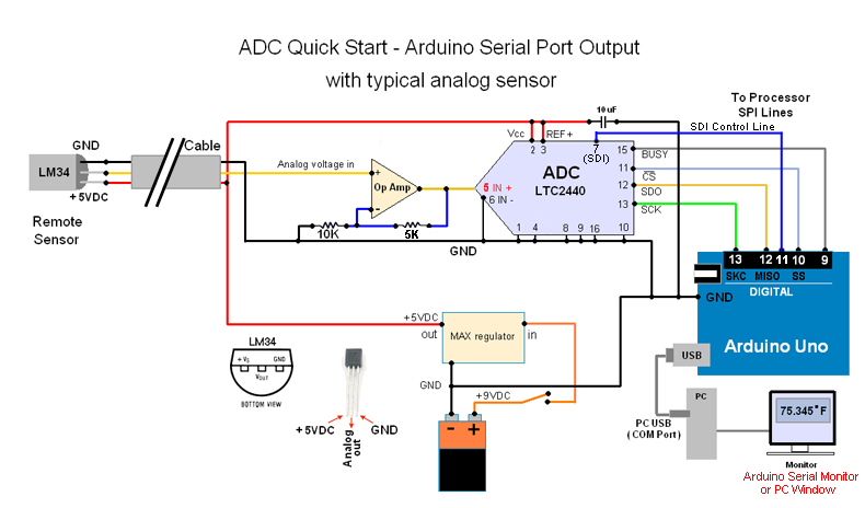
ADC - PROCESSOR SCHEMATIC BLOCK DIAGRAM
Surface Mounted Technology (SMT)
I
have repeated this diagram above because it is so important to move
onto more complex application of the 24 bit ADC. In this diagram above,
you can see the analog signal is sensed by the green device which can
be a temperature sensor, or humidity sensor, or motion sensor, etc. The
orange analog data is represented by the number 12940328 but this could be any analog number such as 39.8093 Degrees C. The signal is then adjusted and, amplified in some cases, and then the analog signal enters the ADC. Inside the ADC, the signal is converted to a digital value represented by the orange zeros and ones in the diagram on the right. In this case, the Arduino does a little more work on the signal and sends it to the PC which also processes the signal, including converting the number to the original analog value that entered the system and then displays the original analog value on the screen. A SPECIAL NOTE ABOUT LTC2440 SSOP (SMT) SOLDERING!  If
you have never worked with SSOP chip sizes you are in for a rude
awakening. SSOP is a tiny surface mounted technology (SMT) IC and
can be extremely difficult to solder if you do not have the right
soldering iron and some experience soldering micro circuit components.
The best way to start is to look at a few videos on "SSOP soldering".
In the image to the right is a 16 pin chip very much like the LTC2440. If
you have never worked with SSOP chip sizes you are in for a rude
awakening. SSOP is a tiny surface mounted technology (SMT) IC and
can be extremely difficult to solder if you do not have the right
soldering iron and some experience soldering micro circuit components.
The best way to start is to look at a few videos on "SSOP soldering".
In the image to the right is a 16 pin chip very much like the LTC2440.Try this address for a start, some of the videos are quite good but soldering can be a tense and scary process the first time. Here is a place to start on YouTube: https://www.youtube.com/results?search_query=ssop+soldering I generally solder to an adapter board which has pins on both sides and allows you to plug the soldered ADC/board assembly into a breadboard type of circuit test bed. - THIS IS A GREAT GENERAL SOLDER TECHNIQUE VIDEO below - the whole video is excellent: https://www.youtube.com/watch?v=3NN7UGWYmBY This is the best video I have seen on soldering very small surface mount components such as the SSOP/narrow pad types.The only problem is the person is very good at this stuff! I have probably watched this 10 times so far. Watch lots of the demos - they are mostly, very good. One detail with which you should take care. Technically the LTC2440 size is called a 16-Lead Plastic SSOP (Narrow .150 Inch). Most, but not all, standard SSOP board patterns will take this "Narrow" class. | This address downloads the .PDF data sheet with exact pad
dimensions: www.linear.com/docs/3135 on page 27. In soldering SSOP, the most important issue I found was to have a sharp soldering tip at 40 to 50 watts and good magnification of the chip pads to be soldered and iron temperature control if possible. I find it is important to have a fairly hot tip which melts very fine solder quickly and avoids over heating the chip waiting for the solder to melt. This sounds backwards to the pro assemblers but speed, very fine solder, and pre-rosin pasted surfaces are important. Excessive application of rosin paste can cause the solder to bridge the pins. These points (so to speak) are critical in order to avoid over heating the IC.  Also
important for me - have some "desolder" woven copper
braid ready - you will need it to clean up your solder overflow unless
you are very good with an iron especially if you have an unwanted
solder bridge between chip legs. Also
important for me - have some "desolder" woven copper
braid ready - you will need it to clean up your solder overflow unless
you are very good with an iron especially if you have an unwanted
solder bridge between chip legs. This is a very good video but be careful with the pad dimensions of the LTC2440 (SSOP/Narrow) - this company may not sell a pre-soldered board of the right dimensions. https://www.youtube.com/watch?v=-32orELxkpE Practice with your iron on very tiny wire joints BEFORE you try to solder the 2440 and get a feeling for the melting point of the solder and the flow characteristics of the rosin paste you are using. If the solder is just not melting, quit and try soldering again. PRACTICE -- just a few seconds of heat applied to long to a pin on the chip will destroy the chip! But it is better to study a few videos - some of the people making the videos are very good. Always keep the tip of the iron clean - I keep a small bit of fine cloth sandpaper near by. Cleaning the tip on a wet sponge is even better. When you are done, use some kind of continuity checker to check each pin for a connection to the pad and check that each pin is independent - no soldered to a pin next to the intended pin. I do use a high power ocular but the ultimate check is continuity where it should be and none where it should not be. But be careful with the continuity checker voltage applied. Please keep in mind that this soldering is easier than it first seems and is extremely useful once you develop confidence and some experience working with it. You can place entire circuits in a tenth the space you took with wired components especially if you are making your own circuit boards. The entire LTC2440 block diagram shown above, as a printed circuit, can placed on a one inch square (2 cm x 2 cm) board if you break at the input senor and the Arduino control wires but only if space is critical! | ||||
CODE
NOISE ISSUES | |||||
|
Based on my work and others who have written to me it is now possible to
reduce noise with good components and careful wiring, and sensors in the
high nanovolt output region can be read with reasonable signal to noise
ratios (See the
"NOISE"
section below). I have gotten hints from others that they are in the high nanovolt region and approaching 50 nanovolts for analog signals read by systems much like this block diagram above. The region shown in a red tint box is the area where all possible care must be taken for both EMI and thermal issues. If possible, the preamp and ADC should be fully enclosed in a grounded pure copper housing. I suspect it will be necessary to cool the copper housing using Peltier cooling hardware to get to the lower nanovolt regions! But cooling can be risky because of condensation issues so it is not as easy as it might sound. Remember that the gain of this system can reach one million. And the goal of the design is to keep noise in the low microvolt and even high nanovolt range. With good grounding and shielding techniques nanovolt noise is possible. An additional benefit of the enclosed components is less thermal drift from air movement over the components. This air movement over the electronics including resistors and capacitors is significant and can easily degrade an input signal by doubling the drift, especially with the ADC and resistors if "zero drift" op amps are used. In the "quick start" examples below, a high quality "Bourns" (or equivalent) 10 turn pot is critical for a good stable zero at the ADC input stage - beware of cheap imports!!! A cheap pot can actually introduce noise to a circuit and the hysteresis is huge. |
High quality metal film resistors are critical and the better the
matching on the differential amp the better. I typically will match
resistor pairs to better than 0.1% using measured selection with my ohm
meter. For the few caps used find the best quality your budget can
afford - it is money well spent! The next step up for reduced noise is circuit board ground plane design including ground surrounds for critical points. Linear Technologies has some very good documentation on low noise practices even in the LTC2440 and LTC1052 data sheets. Highly recommended reading: LTC2440: http://www.linear.com/product/LTC2440 24 bit ADC LTC1052: http://www.linear.com/product/LTC1052 Zero drift op amp Linduino: http://www.linear.com/solutions/linduino This is the new coding system created by Linear Technologies (LTC) and Arduino The best results I have seen documented using the LTC2440 is 20 bits or one part in one million. If anyone out there gets to 21 bits, please send me an email and let mew know how you got there. If your work is that good, I would like to share some of your methods in this paper with or without your name depending on your preferences. I do recommend meticulous power supply quality. I typically will use a supply with 3 levels of regulation and the last regulation stage includes a relatively high current, five volt reference voltage chip made by Maxim. | ||||
| QUICK START SCHEMATICS |
A VERY BASIC WAY TO TRY THE LTC2440
An absolute minimum circuit
But be very careful. This circuit is very primitive and a single error could damage the ADC. The basic idea here is to simplify the ADC startup and coding to an absolute minimum. The problem with this circuit is that it uses the five volts from the Arduino board which is from the PC. This source of voltage to drive the ADC is extremely noisy. The absolute maximum voltage at the LTC2440, pin 2,3, and 5 is 5 volts. It is best to input less than 5 volts at pin five because 5 volts is so close to damaging the chip.
| LTC2440 ADC Input Voltage Limits |
In the diagram below the ADC
(LTC2440) input voltage must be limited to +/- 0.250 volts.
This limit is not a serious limit because most applications of this
system are working with microvolt and even nanovolt source voltages.
When the overall system gain is considered, ADC output voltages of +/-
0.250 volts would be welcome. And in most cases, a simple gain increase
in the ADC code will produce any number needed within reason.
The limit is from the requirement of the ADC to process a signal from -0.3 to + 5.3 volts. Any one needing to work with data in the one to five volt region should divide the ADC input voltage by 10 with precision resistors, and correct the division in their ADC processing code using 10x in the gain. It is possible to offset the input voltage by adding +2.5 volts to the signal but this +2.5 volts "offset" can be a major source of new noise. I have tried both solutions - working with a voltage under +/- 0.250 volts and the +2.5 volt offset, and I found it is far easier and cleaner to simply work at less than +/- 0.250 volts as an input voltage. |
If the ADC does not show a voltage in the Arduino serial monitor, try a higher voltage source impedance - switch the 10K fixed resistor to 100K.
A better circuit would use a pot output from a 1.5 volt or 3.2 volt battery. It would also be safer to place a buffer op amp between the input voltage ( the source) and the input of the ADC. I strongly recommend a buffer amp of some kind even if it is a voltage follower made from any quality op amp to start - even a 741 will work initially. As soon as possible, a voltage reference source should be used for the ADC. The reference voltage is critical to high performance ADC output. The ADC accuracy and stability depend on the quality of the reference source.
I use the Maxim 6250 as a 5 volt reference source. It is a precision source, extremely stable, and can handle a higher current draw than most reference sources. The Maxim 6250 is strong enough to drive two (low current) op amps, and power the LTC2440 ADC as well as act as a reference for the ADC. But the maxim reference requires an input of 7 volts or higher as most references do.
The system readout can be as simple as the Arduino serial monitor window. This kind of basic start will give you an idea of the ADC operation and will also let you work with, and maybe develop better, Arduino code than I will supply below.
An interesting example of this circuit for people just getting started with 24 bit ADCs
 Stefan Schäfer of Heidelberg University sent me this
photo of their prototype and said this was their start in the
Arduino-LTC2440 world.
Stefan Schäfer of Heidelberg University sent me this
photo of their prototype and said this was their start in the
Arduino-LTC2440 world.It shows that everyone, no matter who they are or where they are from must start someplace. The image to the right is a photo of their first bench prototype. They have since upgraded to a regulated power supply and a few other improvements including the code shown below on this page. This is very much how I started my investigation of the 24 bit ADC - tape, a few wires, minimal components, and a quick test!
Mark in Australia started his project very much like this. Within a few days Mark was improving code and adjusting his ADC circuit to fit his needs.
In the engineering world this is called "proof of concept".
This is how anyone can make a 24 bit ADC work with a minimum of effort and cost - about $40 including the Arduino board. Once the basic idea of the 24 bit ADC is working a kind of plateau is reached. The initial fears of hardware and software issues are past, and the real project can start.
As crude as this seems, this is a very nice way to move forward in small, simple steps to make the 24 bit ADC an easier and very "doable" project. Get rid of the intimidation - start simple and get the ADC running - the rest is easy, and fun.
A much more detailed photo with connection information is available as a new window along with some suggestions on how to build and improve this circuit. Click here or on the image to open thenew window with a better photo.
If you wish to email Stefan, the builder of this prototype and the author of the Arduino/Linduino code below, his email is:
schaefer (at) iup.uni-heidelberg (dot) de
A second version of the simple start-up circuit
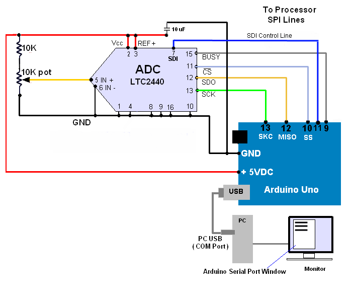
| A VERY SIMPLE ADC/ARDUINO AND OP AMP
CIRCUIT TO MAKE A FIRST ATTEMPT AT RUNNING AN LTC2440 ADC INCLUDING A SIMPLIFIED ADC CODE LISTED BELOW Using
this Circuit:
The LTC2440 will fit on most SOIC circuit adaptors. Soldering a chip to an SOIC board is difficult...please read what you can find on soldering methods with SOIC components. When soldering a chip to an SOIC board, it is extremely important to check for continuity of each pad to the chip and to also check for solder bridges between pins. Either error can cause an error and worse can cause chip destruction!!! Use any op amp available as a buffer to help protect the ADC chip. If you have high performance low noise op amps available use them in this circuit as soon as you have tested the circuit and it is working. I use the LT1028 in later examples of low noise circuits. But I would suggest that you use a modest op amp until you are sure your circuit is working and will not damage the op amp or the ADC. A high quality pot will give you better results than a cheap pot but either will work. Do NOT ever use a voltage over 5 volts in this circuit - it will burn out the LTC2440 instantly. 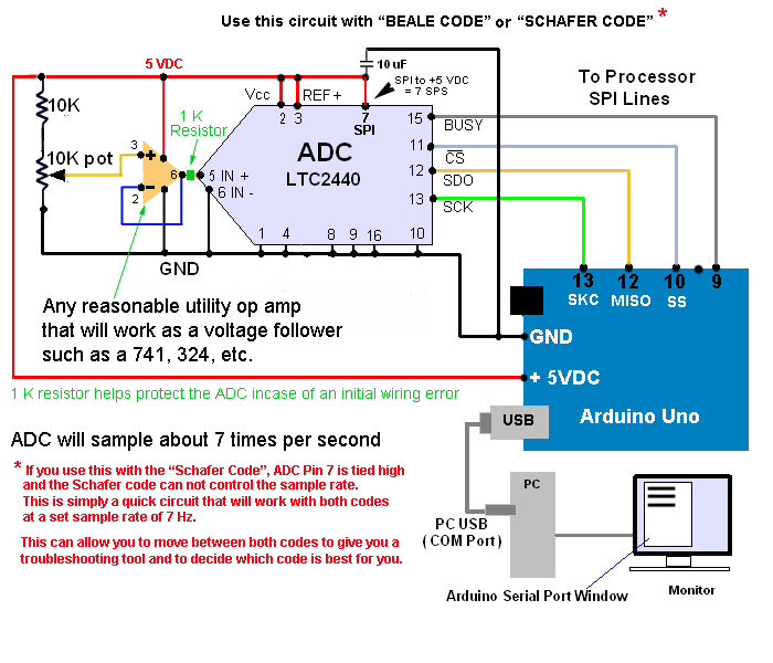 |
|
CODE
TO GO WITH THE CIRCUIT ABOVE for a copy of the actual code go to the "Coding" section on this page and look for the "Beale code". For a copy of the Schafer Code go to the same section and look for the Schafer code. The differences between the code is explained on the coding section |
NOTE: To adapt this circuit to the Schafer code, wire the LCT2440 ADC, Pin 7 from hard wired to + 5 volts, to Pin 7 of the ADC hard wired to the Arduino Uno board Pin 11 as the blue line in the schematic belows shows.
A BETTER WAY TO START - but a little more complicated...
A better power supply
The Maxim regulator chip series is excellent for low noise and will provide a higher current limit than most precision voltage sources. But any high quality five volt reference voltage regulator chip will work.
The data sheet for the Maxim chip is here:
http://www.maximintegrated.com/en/products/analog/voltage-references/MAX6250.html
I would also suggest the use of noise suppression caps (2.2 uF) as shown in the Maxim sample circuits.
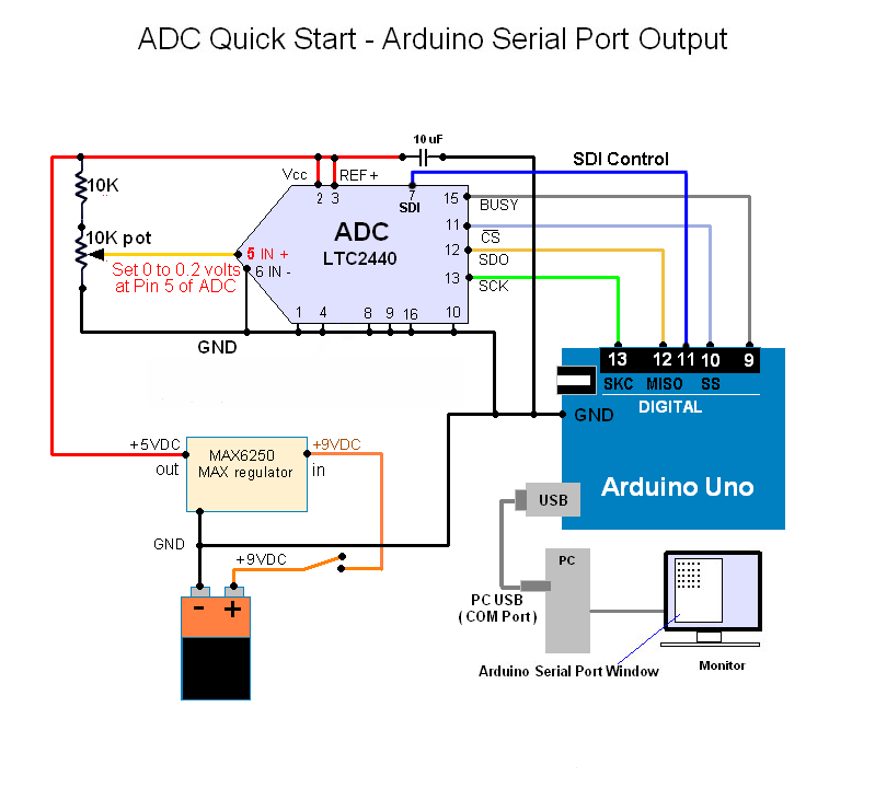
THE BEST WAY TO START
USING AN OP AMP AS A BUFFER BETWEEN THE DATA SOURCE AND THE ADC
The op amp can also act as a pre-amp for very low level sensor outputs where the gain can be set to 1000 or even 10,000. Higher gains can be obtained with low noise, low temperature drift op amps such as the LTC1052.
A second op amp can be added to act as an output zero to the ADC by using a summing op amp circuit configuration on the 2nd op amp input. The op amp +5 volt power can be drawn from the Maxim voltage regulator as long as total 5 VDC circuit current draw is within the limits of the Maxim regulator chip specs.

The Arduino serial output can be fed to the Arduino Serial port as shown in the above diagrams or fed to a PC/MAC/LINUX system capable of reading a serial input from a com/USB port.
SPECIAL NOTE: The reference source voltage for the LTC2440 Many people have asked what to use as a reference voltage source. The first point to make is that you can use any ultra-stable 5 volt DC source - even a battery. Just keep in mind that batteries tend to drift with temperature. If you prefer to use a separate source from the ADC power supply - do it. The diagrams on this page are written to give you a quick start, not a final design. These circuits are seeds not final designs. I have always found that publications of complex circuits are so carefully drawn to account for all possible situations, that the final circuit can be two or even three times as complex as the basic idea of the circuit. Another example of complexity not directly related to function is coding input error checks. You are free to enhance the code in anyway that will work for you. As for reference voltage sources, the only limitation I would take great care with, is the current capacity of the reference source. I have had voltage reference chips bog down when the current draw is two high. In this circuit, finding a variable reference voltage source failing because of heat or excessive current draw is a VERY difficult problem to find. You are free to use a separate current source for each critical voltage need if you feel the added circuit complexity is worth it. As for specfic reference voltage chips I do like the Maxim MAX62xx series such as the MAX6250, 5.000 volt reference for a well controlled 5 volt output at up to 15mA found here: https://www.maximintegrated.com/en/products/analog/voltage-references/MAX6350.html If you are going for 21 bits or higher, I would suggest the best possible voltage reference sources available. By the way - reference voltage sources are changing almost daily so be careful to find state of the art chip designs. LTC (Linear Technologies) and TI also make a selection of good reference sources. Thermal stability, current output, and noise are important considerations. |
| THREE WIRE SENSOR SCHEMATIC |
TYPICAL 3 WIRE ANALOG SENSORS
This circuit is also much like a typical MEMs accelerometer for G force measurements and for compass sensors. A good magnetic field sensor could measure direction using the earth's magnetic field to a tenth of a degree.
Keep in mind that an analog measurement should be reliably measured to one or even two places more than the measurement readout to assure good accuracy.
And LM34 is a Fahrenheit device and an LM35 is a centigrade device. The LM34 shown here will output a voltage one one-hundredth 1/100 of the actual temperature reading. So if the LM34 outputs a voltage of .75344 volts the temperature will be 75.344 Fahrenheit once the LM34 is properly calibrated. Gain and offset can be set in the Arduino code. A high quality (1%) LM34 would have a gain very close to 100 and an offset very close to zero.
Please Note: The op amp in the circuit below must be very temperature stable or the voltage output will be proportional to both the changes in the LM34 and the changes in the op amp. I recommend the use of the op amp series called "Zero Drift" because they are extremely stable over an environmental change of 100 degrees C.
IMPORTANT NOTE ABOUT THIS LM34/LM35 SCHEMATIC
| DIFFERENTIAL AMPLIFIERS |
AN IMPORTANT MESSAGE ABOUT THE VOLTAGE INPUT LIMITS OF THE LTC2440 ADC
 There
is a critical configuration of the LTC2440 that must be
understood before a voltage is applied to the ADC and its surrounding
circuit.
There
is a critical configuration of the LTC2440 that must be
understood before a voltage is applied to the ADC and its surrounding
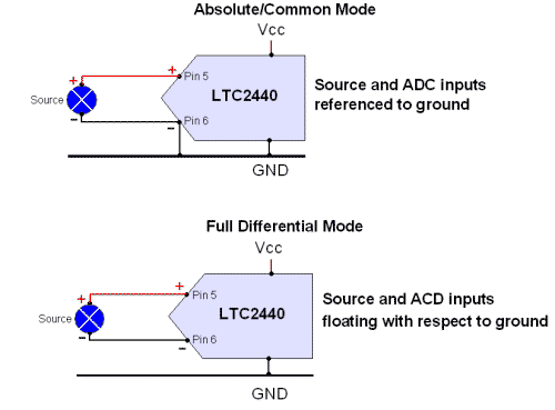
circuit. Will the LTC2440 be wired in an absolute/common mode device configuration or will it be wired as a full differential device? It is extremely important to know the difference and design the circuit accordingly before a voltage is applied to the circuit!
ABSOLUTE/COMMON MODE (upper circuit to the right, grounded Pin 6 of the ADC)
In the absolute/common mode, the voltage applied to the ADC from the sensor is limited to a range from -0.3 volts to Vcc + 0.3 Volts. Any voltage more negative than - 0.3 volts can damage or destroy the LTC2440. Any voltage over Vcc +0.3 volts can also damage the ADC. The reality of this circuit is that the source voltage is effectively limited to 0 to + 5 volts in most applications of the ADC.
FULL DIFFERENTIAL MODE (lower circuit to the right, floating Pin 6 of the ADC)
In the full differential mode, any voltage from the source ranging from +2.5 volts to - 2.5 volts can be applied to the ADC. There is no reference to ground at any point from the source to the input and this includes all components between including op amps. Nothing can be referenced to ground on the input side of the ADC in the full differential mode. The exception here is the use of a "fully differential" op amp used as a buffer between your source the final input to the ADC. But you must be meticulous with this buffer to be sure there is no ground reference after the buffer.
"WORK-AROUNDS" USING THE ABSOLUTE/COMMON MODE CIRCUIT LIMITATIONS
 There
are several ways to use the upper right "Absolute/Common mode" circuit
and work around the input voltages limitations mentioned above.
There
are several ways to use the upper right "Absolute/Common mode" circuit
and work around the input voltages limitations mentioned above.1. The first is that the "Absolute/Common mode" circuit does allow up to a -0.3 volts as an input. This then would allow a ± 0.250 volt input allowing a small voltage (± 0.07 volts) excess as protection for the ADC. The problem with this idea is the huge waist of the voltage range lost in limiting a ± 0.250 voltage from the source.
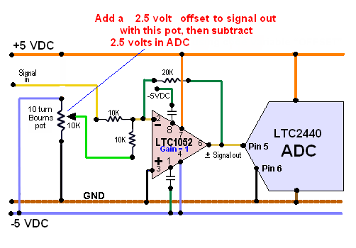
2. A second "work-around" is to add a 2.5 volt offset to the source voltage which will place the input voltage halfway between the lower limit of zero volts and the upper limit of 5 volts. The coding can then subtract the 2.5 volt offset and send a ± 2.5 volts max output from the ADC. This idea would allow a full ± 2.5 volts to be applied to the ADC. Any errors from the source or in the offset voltage would destroy the ADC in seconds.
This is a possible solution and places the input zero point at 2.5 volts allowing a full ± 2.5 volt variation in the grounded source (and preamp) voltage. This gives me a ± 30,000 count range in AmaSeis. Since I am on the the inverted input of this summing amp, I needed to use -2.5 volts as an offset in this schematic. There is a preamp set to a gain of 1000 not shown before this op amp.
 I
am using
this solution and I recommend this to others as a quick and simple
solution to the risk of an out of range voltage getting to the ADC and
damaging the chip but the noise contribution in a high performance low noise
circuit is to high a price to pay.
I
am using
this solution and I recommend this to others as a quick and simple
solution to the risk of an out of range voltage getting to the ADC and
damaging the chip but the noise contribution in a high performance low noise
circuit is to high a price to pay.This voltage problem was brought to my attention by an engineer in Indonesia who had experimented with a negative 1 volt to the ADC and discovered a potential chip damage problem and wrote to me asking for clarification. Thank you Dave for bringing this issue to my attention! I very nearly destroyed my ADC testing his findings!
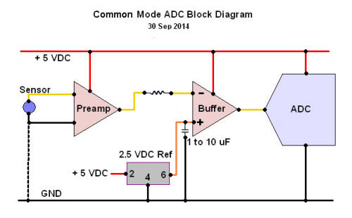
The diagram to the right labeled Common Mode ADC Block Diagram is a simple method to add 2.5 volts to the ADC input and to extend the ADC output to a full ± 2.5 volts. This means the ADC, if wired as it is shown to the right will accept up to minus 2.5 volts without damage to the ADC. Remember that the entire ADC is using the 2.5 volts offset so any noise or variation from the reference source will translate directly 1:1 into ADC voltage variations. The higher the quality of the reference and five volt source the cleaner the signal!
I have tried this 2.5 volt offset solution and it does work - but with extremely high gain applications (one million or more), any variation in the offset voltage will cause shifts in the output data from the ADC, probably caused by temperature variations affecting circuit components. I believe the 2.5 volt offset reference source must be of the highest stability possible.
A SECOND SOLUTION - A "FULLY DIFFERENTIAL OP AMP"
What is a "Fully Differential" Op Amp?
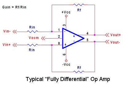
I am presently studying the LTC6409 shown here. Standard differential op amps will not work because their output is usually referenced to ground. The 6409 is one of many amps of this type. I am simply thinking in terms of the 6409 as a possibility.
The "fully differential op amp" can be used as a buffer between a ground referenced source or a source and preamp which are both ground referenced.
Back to the LTC2440
The point of the comments made in this section is that it is EXTREMELY important to never place voltage more negative than - 0.3 volts on the ADC with the ADC and source wired to a common ground. A excessive negative voltage can easily destroy the ADC is seconds!
Where this voltage limit is found in the LTC2440 Data Sheet
All of this input voltage information comes from a very modest, somewhat confusing statement in the LTC2440 data sheet on the lower right side of the data sheet, page 10 and 11 - go here: http://www.linear.com/product/LTC2440 and download the Data sheet.
If anyone reading this section who disagrees, please write...I would be very interested in what might be wrong or changed.
| 24 BIT VOLT METER |
A GENERIC HIGH GAIN PREAMP AND ADC CIRCUIT FOR MICROVOLT AND LOW MILLIVOLT MEASUREMENTS
Some sensors will need a ground reference and +Vcc to drive the sensor. In the circuit below the second op amp has a single ended output fed into the ADC.
If the sensor requires +5 VDC, include the circuit five volt line in the cable to the sensor on the left side of this schematic. Do not ground the sensor, especially at the sensor end, unless absolutely necessary for the operation of the sensor. Floating the sensor into the differential amp input will greatly reduce cable noise (common mode noise) and stray EMI picked up by the sensor cable. Try to ground the sensor at the preamp if a ground is essential. Grounding the sensor at the sensor end and at the preamp end can cause serious ground loops.
Please note that this schematic uses the LT1028. I have tested this op amp and it has an extremely low noise level and very good temperature stability. It is now my preference over the chopper stabilized op amp (LTC1058). Consider using a chopper stabilized op amp if your system is exposed to outside air temperature variations. If in doubt, try both for your application. The noise spec for the LT1028 is in the nanovolt range and about 1/10th the noise of the best of chopper stabilized op amps.
 This schematic also is best used where the source (sensor) voltage is in the
nanovolt or low microvolt region. Because the preamp has a gain of 1000, it is
best not to use this circuit with source voltages over one millivolt (0.001
volt). Reducing the preamp gain will allow source voltages up to 200 millivolts
(0.2 volts).
This schematic also is best used where the source (sensor) voltage is in the
nanovolt or low microvolt region. Because the preamp has a gain of 1000, it is
best not to use this circuit with source voltages over one millivolt (0.001
volt). Reducing the preamp gain will allow source voltages up to 200 millivolts
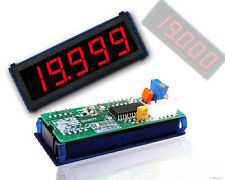
(0.2 volts). BUY A PANEL METER - a strange way to start this section!
It sounds like this is not a meter schematic plan but an ad to buy one - it is NOT. It is simply a good idea to buy a millivolt digital meter to monitor the input voltage to the 24 bit meter ADC - it is an essential tool especially at nanovolt input levels to the 24 bit meter! If you are trying to measure nanovolts you will be blind until you have amplified the source voltage by 1000 at least. The monitoring meter should be accurate to 4 or more places after the decimal. Four place digital millivolt meters, as a bare bones "panel" meter, are available on the market for $10 to $20 (US). They are extremely useful as a test, troubleshooting, and sensor monitoring tool. I realize it sounds strange to buy a panel meter to build a volt meter but if you study the meter circuit below you will realize you are will have no idea what voltage is entering the ADC at Pin 5 ( IN + ). The meter will help you set the gain of the volt meter and help you protect the ADC from over voltage at the ADC input. Be very careful with the panel meter you purchase - some "panel" meters, especially on EBay, do not measure negative voltages. The meters just show all zeros at negative voltages - crazy - at least they could show the term "ERROR"! A version of the meter to the right is featured on Ebay and will not show negative voltages and negative voltages to the ADC is what we are most concerned about!
The photo to the right is a typical meter and this type and allows the user placement of the decimal point. I have found the accuracy of the last place to be questionable but it does depend on your source - ironically it depends on the accuracy or resolution of the meter ADC!
The circuit below is an ongoing effort and I have gotten assistance on the front end and low noise components from a friend who is a senior design engineer. More updates to this circuit will happen in the net few weeks.
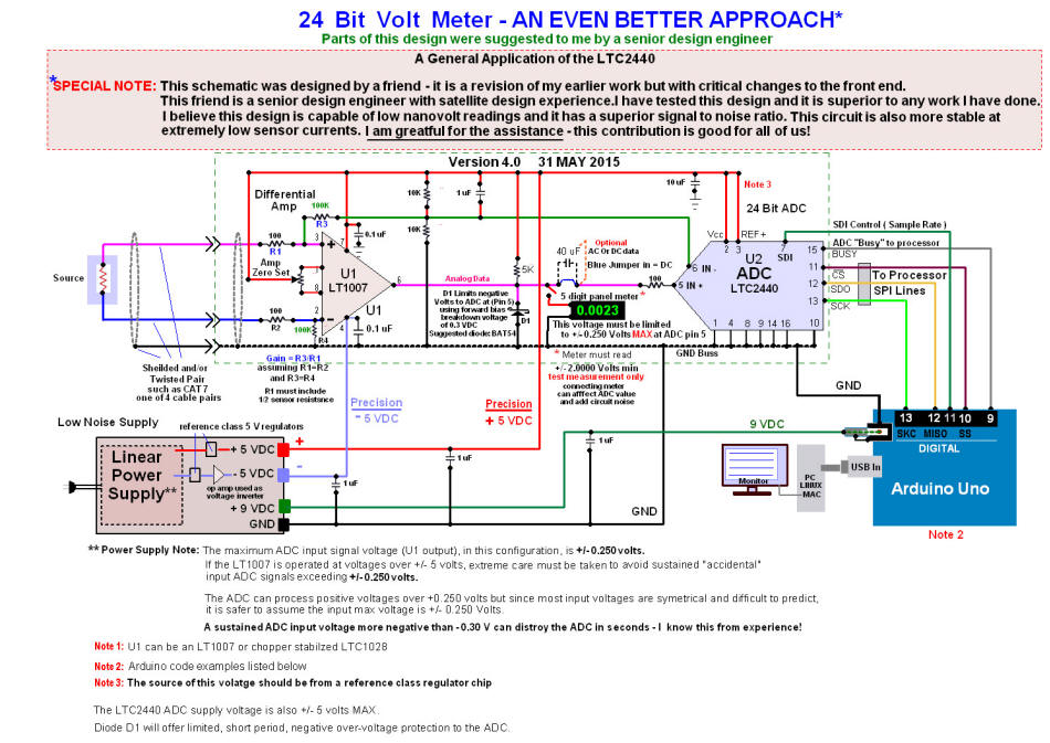
This schematic is shown as the design that is wired for the Schäfer code where the ADC SDI (Pin 7) is controlled by the Arduino board. If you prefer to use the Beale code, either hard wire Pin 7 to ground where the sample rate is 880 sample per second or wire Pin 7 high (to +5 VDC) for a sample rate of 6.7 samples per second.
Diode D1 is clamping diode placed to limit the negative voltage to the ADC. A good choice for the D1 diode is a Schottky diode BAT54. D1 will turn on at its forward bias voltage and clip any voltage more negative than - 0.3 to -0.4 volts. The forward bias of the diode used should be between +0.3 and +0.4 volts. In the schematic configuration the diode will clip a negative voltage from the op amp at - 0.3 to -0.4 volts until the voltage is above -0.3 volts. I would like to place a red LED in the schematic to note the voltage has being clipped but the design involves an added transistor and becomes to complex for this startup schematic.
I have found it necessary to use a linear power supply because the linear design has far less high frequency noise and my noise measurements show that the output noise using a switcher driven supply is about twice as noisy as a good, well filtered, linear supply.
If you expect the op amp to be exposed to wide variations in temperature (more than 30 degrees F variation) , I would suggest using the chopper stabilized LTC1052. The LTC1052 is almost pin compatible with the LT1007. The difference is with Pins 1 and 8 which do not allow op amp output zero. Pins 1 and 8 must be wired with 0.1 caps to ground or the negative supply depending on the power supplied to the amp. The pin 1 and pin 8 caps are critical and leaving pin 1 and pin 7 open can destroy the chip.
The LTC1052 data sheet is here: http://www.linear.com/product/LTC1052
NOTE: This page also has a detailed explanation on the calculations of the op amp gain, the ADC gain setting (decimal shift), and the ADC output reading with known source voltage and op amp and ADC gains.
| SEISMOLOGY |
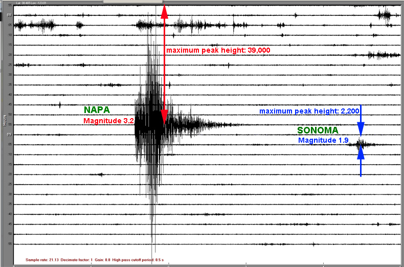
This image below is an example of a seismograph and more importantly it explains one of the great values of a 24 bit ADC.
Click here to open a new window written to explain the use of an ADC in a very wide range of analog data values using seismology as an example.
For more events from my seismograph and my seismograph construction detail, please visit this separate page:
http://www.steveluce.com/24bits/index.html
| NOISE |
I have been working with this op amp and ADC circuit for about 2 years. I have made a number of noise measurements over time and they have steadily improved as I have concentrated on reducing noise sources. I have a long history of noise measurements but old noise measurements are of no value except the history of the changes. So I will only show the latest information. I will say that noise has gone down with circuit improvements by a factor of 100.
 Present noise appears to be in the nanovolt region. My original noise
measurements showed noise in the low microvolt range.
Present noise appears to be in the nanovolt region. My original noise
measurements showed noise in the low microvolt range.In the past month I have written a noise test program (the chart to the right) using "Processing.org. The essential problem is how do I measure noise at a level well beyond my test equipment. As my system noise goes down, my ability to reliably measure nose has become extremely difficult.
I finally was forced to measure noise and graph the noise without really being able to confirm the actual levels because the noise is far less than my modest oscilloscope scope and volt meters will measure.
The next best way for me to approach noise measurement is to graph the noise and then to try to calibrate my graph. I was able to make a reasonable calibration of the chart and the chart is show to the right.
I believe the data in this chart is accurate but I can not absolutely confirm the accuracy of the chart. One confirmation of many I made was to generate a one microvolt signal generator and read the voltage from that generator. The magnitude of the generator is in agreement with this chart.
The measurements to the right were done with a low noise resistor in place of a source voltage to my voltmeter schematic shown above.
I did start this measurement process with a good quality "switcher" power supply. I then measured significant high frequency noise with my scope and went to a high quality linear supply. The linear supply reduced the noise by a factor of two.
I also asked a former satellite design engineer I know, for some guidance and he made a number of component suggestions including the backbone of my project the LTC2440. He also suggested the use of an LT1007 op amp which has an extremely low noise level. These suggestions and many others have been extremely valuable.
The results in the noise chart to the right are well above the minimum noise levels of the components so I still have a lot of work to do to reduce noise. I am now concentrating on circuit layout, grounding, EMI shielding, etc.
The important point to this chart is that the volt meter circuit shown above is capable of measuring down to the low nanovolt region if a signal to noise ratio of five to one can be accepted. This measurement must include a good averaging component in the code. It also requires a low sample rate of 12 samples per second or less. In fact the noise levels in the chart can be cut by half just by reducing the sample rate from 12 samples per second in the chart to 6 samples per second and a doubling of the average from 100 sample per readout number to 200 samples averaged per ADC serial out value.
I would be interested in any suggestions for a nanovolt signal generator or any suggestion to reduce my system noise - code or hardware.
| CODE SETUP ON THE LTC24XX FAMILY ADC |
Below (in blue and between the green lines) is a very nice program written by Stefan Schäfer of Heidelberg University. This code is exceptional in several ways.
- This code uses the new "Linduino" set of libraries created in a cooperation between Arduino and Linear Technologies.
- The code is extremely compact but has been tested with the LTC2440 and works perfectly.
- Part of the importance of the code below is that it uses an averaging operation that further reduces noise.
- The code was supplied courtesy of Stefan Schäfer as a contribution to this website as well as to use in his work in the development of a mass spectrometer high gain sensor using the Arduino/LTC2440 circuits.
A library missing error: This will be a common problem and it will take time for people to use the new to the LTC "Linduino" libraries. The complete complete set of libraries can be downloaded here:
Download the Linduino Library (Library only - please follow Quick Start Guide for instructions on install)
Download and save the LTSketchbook.zip. Keep the entire LTSketchbook.zip file for future use. To make the code below compile, Install only libraries listed in the code below. Make sure your Arduino program "INCLUDE" listing matches the include listing at the top of the program exactly as shown below. Any order of include libraries is acceptable. Once you have this set of libraries loaded, your program should compile. This software will automatically look for a com port to which your Arduino board is connected. If your Arduino board is active and sending data to the serial port and being read by your PC, you will get a com port busy error.
Com port busy error: A second more obvious problem is "com port busy" is easy to solve. You probably have a device reading or sending data to a com port and the data is being read by your PC - turn off the send or read data operation in your PC. But if you are using these circuits, do not turn off the devices - just stop the read process in your PC.
Typical code to run the ADC with the start-up circuits above
How to Use this code
The code below is but tested. it is extremely effective with the LTC2440 and gives the user control of the sample rate using the internal timing set by the SDI pin 7. Using this pin can assure the lowest possible noise level for the user's particular needs.
Code Variable Setup
Sample Rate (Sample per second or SPS)
Determine the slowest possible sample rate that will work form your application - the lower the sample rate the lower the ADC noise contribution to the signal. It is best to select a value like 64 in the line:
static int16_t OSR_mode = LTC2440_OSR_128;
Start with... LTC2440_OSR_64. The number in red is the sample rate input to set the 2440 internal sample rate (SPS). If the sample rate is to low try a higher number from the list such as 128 which is where this code is set. Eventually you will find a rate that will for for your application. The actual sample rate will vary with the application, the computer reading the serial data and the program in the computer and the permissible baud rates in the application.
This is the reference voltage used in the ADC circuit. Most LTC2440s will use a Vref of 5 volts. If Vref is 5 volts set the line as:
static float LTC2440_vref = 5.0; Where 5.0 is the Vref value
nsamples
This is the number of samples averaged into a single serial sample output of the ADC. A value of 100 means that 100 samples of the ADC are averaged and a single number output which is the average of the 100 samples taken. The output of the ADC is a sequence of samples with each sample group with being 100 input samples. This number is extremely important and should be as high as possible. This number can significantly reduce noise using s smoothing process. A value of 1 would mean that each number created by the ADC would be the number output as a voltage. the value of 100 is a very good place to start. Using 100 would look like this:
const int nsamples = 100;
Any data smoothing algorithm can be sued here. The present average is simply:
(each sample in nsamples summed to a total value) / (nsamples)
NOTE: There will be a balance needed between the sample rate and the number of samples averaged. If I try to output at a very low sample rate with 100 number per average set, I get an output sample rate of 3 SPS. If I lower my nsamples to 50 and raise my sample rate to 128 my real sample rate to 18 SPS. If your input voltage less than 100 uV and low noise noise is critical, try to keep your sample rate as low as possible and set your sample size to 100 or more, if possible, for a very low noise contribution from the ADC.
GAIN, OFFSET, and Volts_Out
GAIN and OFFSET are in this code to allow calibration of any linear voltage source. These variables are in the code to be used in the linear equation Volts_Out = a*x +b. where "a" is GAIN and OFFSET is "b". If you do not know the expected output line or curve shape set GAIN = 1, and OFFSET = 0.
If you are curve fitting a sensor or creating an equation to fit a sensor output
In terms of the shape of the sensor output as a graph of the data, and assuming a linear sensor input, GAIN is the slope of the sensor output line on a graph and OFFSET is the shift from zero, plus or minus. More complex sensor output curves can be entered in the code, in place of "ax+b", but the key is in finding an equation that will approximate the sensor output voltage over your range of interest. It is most often, an iterative process.
DO NOT APPLY A NEGATIVE VOLTAGE MORE NEGATIVE THAN -0.3 VDC TO THE ADC PIN 5, USING THE CODE BELOW UNLESS THE LTC2440 IS IN A FULL DIFFERENTIAL MODE (Pin 5 and Pin 6 ) must be floating with respect to ground.
It is common the ground "-IN" (pin 6) and this is where the ADC can be damaged if a negative voltage is applied to the +IN (pin 5).
The code above shows the specific lines for gain and offset. I usually create variables called "gain" and "offset" for an equation ax+b=c where "x" is the analog voltage reading. And in this equation "gain" is "a" and "b" is offset. By selecting or just guessing at the values for "a" and "b", most linear systems can be very well calibrated. Depending on the ADC input, it may be necessary to add some offset value. The offset can come from ground issues and they usually raise the ADC output value by a few tenths of a volt. If the voltage is to high, a negative value for "offset" will be necessary.
A SIMPLE WAY TO MONITOR THE AND GRAPH ADC OUTPUT OF THIS CIRCUIT ON A PC
There are a number of very good programs available for the standard windows 7 PC, Mac, and Linux processors that can input the serial output of this program. Many of these programs are written for various professional applications but will work well with any serial output code on this page.
I am presently using AmaSeis Version 3.2 which tracks earthquakes. But it is really a line by line monitor display which shows input serial data values 24/7 at adjustable data displays from 1 minute per line to one hour per line. The formal serial data is captured and written as .SAC files on a disk. The program then reads from the disk and allows a number of data modifications including magnification and detailed analysis of data sets. This program is free and can be easily downloaded and install on most PCs and Macs. The program never corrupts the original data so any number of processes can be applied to data with no risk of damaging the original data.
AmaSeis generally does best with serial data values from ±1 to ±50. So if you choose to use AmaSeis, adjust the code in the Arduino processor by selecting a data multiplier x in the (v=v*x) line (the line above the return(v); ) of the code above) to output your data with numbers from 0 to ±50
AmaSeis could be used, as an example, to monitor temperature 24/7 with permanent records of the data stored on disk.
Good information on the download and use of AmaSeis is available here:
http://web.ics.purdue.edu/~braile/edumod/as1lessons/UsingAmaSeis/UsingAmaSeis.htm
Keep in mind that the page is written for seismographs but think out of the box - this program can easily be adapted to monitor any analog data! The only adjustment to be made would be to adjust the Arduino code to output data in a range that will work for AmaSeis. There are a number of other free data analysis programs written for specific data graphing and recording, just adjust the serial data value in the Arduino serial data output value using code shown above on this page. The AmaSeis program even has a window for high and low pass filtering and a window for Fourier analysis of frequencies in the data in a linear or log-log format.
THIS PROGRAM MUST RUN AT 9600 BAUD Unfortunately this is an old program and must runt at 9600 - a serious limitation!!!
As a even more detailed example, consider logging a high gain analog signal over a period of hours using AmaSeis. Then select a section of the analog data on the AmaSeis graph and apply a fast, linear, Fourier analysis to the data. You might find that 50, or 100, or 60, or 120 Hz is dominant in the data. You then know your system is picking up lets say 60 Hz noise from the local power source and you can improve shielding, build a hard wired 60 Hz filter into the amplifier circuit, or write a notch filter into the Arduino program - THINK OUT OF THE BOX CONCERNING SOFTWARE TO ANALYZE YOUR DATA.
| INTRODUCTION TO ARDUINO/LTC2440 CODE |
Using the Beale Code (Code to go with these Quick Start Circuits)
Please excuse my simplistic explanations here for the pros who have built many breadboard circuits. My first weeks trying to get a 24 bit ADC running were difficult. I went many weeks with no help except trying various coding and voltage combinations and a lot of emails asking for help until I finally had a legitimate ADC number show! It is my goal to make a 24 bit ADC as simple to wire as a 324 op amp.
WARNING: I strongly recommend that you do not ever place a voltage over 5 volts in the ADC/op amp circuit including test voltage sources. The reason for this caution is that it is to easy to make a mistake in wiring and testing and accidently connecting a voltage over 5 volts to the op amps or to the ADC. As an example, using the 9 volt battery as a test voltage and then wiring a divider pot on the 9 volts. One wire misplaced will wire 9 volts directly into the ADC can instantly kill it. The 3 second rule for dropped food does not apply here! Just be safe and keep all the voltages in the circuit, including test voltages, at 5 volts or less.
This startup section is based on the LTC2440 pin 7 wired to ground. Since the ADC is sampling at 880 sample per second John Beale added an averaging step in his code. This averaging is the variable "n" in the code. The program uses "nsamples" as a divide by number to collect data for "nsamples" samples, average the sample set and print the average. This is also an excellent way to control the sample rate. This means that since the chip internal sample rate is 880 SPS (Samples Per Second) and "nsamples" is set to 44 the output rate or net samples per second output is 880/44 or 20 sample per second. A value for "nsamples" of 100 would give a SPS of 8.8 but each sample has been averaged for 100 samples. I typically use "nsamples=42" which usually gives me something around 20 sample per second with each sample being a sequence of samples averaged for a set of 42 samples.
The code below is written for an output sample rate of 20 sample per second averaging 42 samples per output sample.
Test your circuit ahead of time. If possible leave the ADC out of the circuit and check each pin for voltage. Once your wiring is complete and before you install the ADC, put a volt meter on pin 5 of the ADC and change the pot from one end to the other. Your meter should read from zero to 2.5 volts. When all looks correct, turn the voltage off and install the ADC
Start by setting the pot to zero voltage at pin 5 of the ADC and measure that value with a volt meter on a millivolt scale attached to pin 5. By running the code and selecting the Arduino serial port monitor you should see a series of zeros going down the screen. Remember to set the BAUD rate at 9600 on the serial port reader in the Arduino serial monitor program because the output rate of this code below is set at 9600 on (approximately) line 31 of the code depending on what you include as a line of code.
Starting and checking the ADC
If you do get all zeros in your Arduino Serial monitor, then adjust the pot for a very small voltage and check the volt meter for a slight voltage reading - maybe 20 millivolts. If you see a value change in the serial monitor you have a working ADC. If you increase to one full volt and still see zeros, check your gain third from last line:
v=v*gain+offset;
Try changing the gain to 10:
gain=10;
This will increase the ADC gain by 10 times the ADC input value. If you still get all zeros your ADC is probably not running so you will need to check every pin for wiring and voltage. If you get extreme numbers like "212367434" then your gain is to high so try reducing your pot value to zero and verify pin 5 of the ADC is zero and you should see a number close to zero. Eventually you will have a number that changes with the pot value - your ADC is running - good for you!! The first time I tried to use the LCT2400, and older version of the LTC2440, it took me weeks to get code and wiring right.
Once your serial values are following your pot changes, you can calibrate your gain if you care to by adjusting the gain multiplier to give you a serial output which is the same as your volt meter. You can now do something interesting like connecting a known sensor or by simply holding the pot tightly with your fingers and warming the pot. This system is so sensitive you should see serial values change as you warm and cool the pot because almost all pots are temperature sensitive.
I will attach a sample of code. Most of this code was developed by John Beale and is a great improvement over earlier LTC2400 code that has been floating around on various sites. I have modified this code to produce a simple voltage on the Arduino monitor that should be proportional to the input voltage.
In my seismograph application, an earthquake of magnitude 3.0 in my area will cause a motion of my coil in a strong magnetic field to move the thickness of a piece of paper. So I am routinely dealing with voltage in the microvolt region. I can detect motion in my seismograph that shows measurable activity from a quake of magnitude 6.0 seven thousand miles from my seismograph. Visit the seismograph page if you are curious to read more. The page is here.
Typical 24 bit ADC voltage input
When an input voltage is in the millivolt range a gain of 100 to 1,000 can be applied. Think of the gain number as a decimal shift rather than a voltage gain. This ADC does not amplify the input value it just makes the output number a digital value (24 ones and zeros). So a gain of 100 will make 1 millivolt 100 millivolts or 0.01 volts as an output from the ADC. With a gain of 1000, 1 volt (1.0 volt) would then be output from the ADC.
It is important to know approximately what the input voltage is to the ADC so that a gain will display the full number (all the real digits in the voltage) being measured by the ADC. To little gain or decimal shift will cause you to lose data digits and to much gain will give you output numbers to high in value. Seven digits is about all you should be concerned with. More than seven digits will just mean meaningless noise values on the end of your data. See the "NOISE" section of this page for more clarification on what is real and what is noise.
Here are some "word" equations that might help in trying to determine op amp gain, ADC gain (decimal place shift), ADC input voltage limits, etc.
Where SOURCE VOLTS is the original input source voltage to the op amp/ADC circuit, ADC GAIN is the number of places to shift the ADC input number with the ADC, the op amp gain is OP AMP GAIN, and the ADC output value is the ADC OUTPUT READING as a number output to the Arduino serial port by the ADC (this is the number that will be imported into a computer for processing).
These equations below can be treated and operated on, as normal algebraic expressions.
- ADC OUTPUT READING = (SOURCE VOLTS) * (OP AMP GAIN) * (ADC GAIN) >>> output value at Arduino serial port
- OP AMP GAIN = (ADC OUTPUT READING) / [ (ADC GAIN) * (SOURCE VOLTS) ]
- SOURCE VOLTS = ADC OUTPUT READING / [ (OP AMP GAIN) * (ADC GAIN ]
- ADC input voltage = (SOURCE VOLTS) * (OP AMP GAIN) >>> The maximum safe negative value of this expression is - 0.250 Volts
More information on the use of these equations and examples is here (as a new window): 24 bit schematic page (new window)
If your ADC input voltage is less than 100 microvolts you should use a preamp BEFORE the ADC to put the ADC input voltage above typical circuit noise values of 5 microvolts. 100 microvolts should be amplified by a factor of at least 100 up to 1000. This then outputs values between 100X100 microvolts and 1,000x100 microvolts from the ADC. 10,000 microvolts is 10 millivolts. A preamp gain of 1000 will give you 1.0 volt output (from the original 100 microvolts). This voltage of one volt entering the ADC is easily resolved to 5 places by the ADC and maybe 6 useable places!
I am working on better documentation of this code but better a sample now than a improved documentation version some day in the future.
I have actually copied this code, using a simple text editor, from this page into an Arduino board and this text, as it is below will load, compile, and operate the circuits above.
Another method to determine the ADC input level
A second way to think of the 24 bit ADC is to understand the ADC data output. Once you understand the data out of the ADC you can set a proper input voltage. The 24 bit ADC produces 6 places of usable data, in some cases 7 places. Lets use 6 places to be conservative. Six places simply means the data is 6 digits wide as in 1.23456. If you also understand that the maximum and minimum input voltages to the ADC you can establish a good input voltage using the full power of resolution (6 digits of data). The maximum voltage to the ADC is 5 volts but to be safe set a maximum of 2.5 volts maximum input.
The minimum voltage the 24 bit ADC can use effectively is a voltage safely over the noise level of the components feeding the ADC and the ADC noise itself. A typical noise level of an ADC circuit is about 5 microvolts. So the ADC should have an input voltage high enough that noise does not dominate or contaminate the ADC output data. This is a matter of opinion and a matter of circuit and sensor noise but I would suggest that a minimum voltage would be about 100 microvolts.
This means that the ADC can safely produce data from an input voltage between 100 microvolts minimum to 2.5 volts maximum. So a safe middle conservative voltage range would be 1 millivolt to 1 volt allowing for maximums and minimums from the ADC input (sensor output). I say safe "allowing for source maximums and minimums" considering such source devices as a seismograph where a typical ADC source voltage could be 1/1000th of the maximum voltage and more in a Magnitude 6 event close to the seismograph as I recently experienced with the Napa quake.
A signal can be adjusted down with a voltage divider for voltages over 5 volts. And a signal can be increased with a preamp in a case like a thermocouple source. Be very careful to buffer the ADC because it does perform better with a fairly high source impedance such as the output impedance of an op amp even if the op amp is unity gain (voltage follower).
Summary: A 24 bit ADC data source voltage should be between 1 millivolt and 1 volt for the best possible ADC resolution allowing for ± 100% variations in the source output voltage and with an op amp buffer in front of (protecting) the ADC. If the source output voltage is extremely consistent ( ± 20 % ) , a much wider range in the ADC input voltage range is possible especially with consistent source voltages over 100 millivolts.
The value of this circuit using the Beale code, is that it is very quick to wire and test. The Arduino library call is simple and you can get ADC output within an hour or two depending on how long it takes to wire the circuit. This is what might be called a "quick and dirty" first use of the LTC2440 ADC.
Using this code (BEALE CODE)
2. Remember to include (or add) the Arduino library called "digitalWriteFast.h"
2. The ADC output is in volts (but this needs more time - the code may not output in volts).
3. Use the Arduino "Serial monitor" to view the ADC output
4. As you adjust the 10K pot you should see the serial value in the Serial Window change
5. The ADC will be sampling at 7 samples per second.
6. If possible switch over to the Schäfer Code shown further below - it is a far better code but more difficult to use because of the library elements needed. A complete list of libraries needed and the library download source is listed in the code header - it is worth it but ADC, pin 7 above is wired differently. This code gives you complete control the the sample rate and produces a much lower noise level.
This Arduino code for the LTC2440 that will work in one of two ADC wiring configurations.
1. A maximum voltage at pin 5 (+ IN) of ± 250 millivolts where the LTC2440, -IN (pin 6) is grounded.
2. Or ± 2.5 volts as an input where the LTC2440 is in a full differential configuration of the ADC and the input pins 5 and 6, and the voltage source are floating with respect to the LTC2440 ground.
The good news about this code is that it does go line by line, within the Arduino code system, which makes following the code a bit easier than Linduino code blocks. The BAD news is there there is no control of the SDI line and the 2440 either runs at 880 samples per second or 7 samples per second.
| ***************** WORKING CODE ***************** |
Beale Code and Schäfer Code
IMPORTANT - There are two major groups of code for the LTC24XX including the LTC2440 24 bit ADC in this document.
The first I call the Beal Code developed from Martin Narwath's LTC2400 code in 2009. The second code I call the Schäfer Code.
- Beale code does not allow control of the ADC sample rate but uses only one library. Two hard wired speeds are available, 6.7 Hz and 888 Hz
- Schäfer Code does allow full control of the ADC sample rate but requires a download of the Linear Technologies Linduino Library and the placement of some libraries in the code header.
- Both working and tested codes are listed below
- If you have a choice of codes, the Schäfer Code is always the best choice - always! And Schäfer Code is well worth the extra effort of installing the Linduino code libraries.
Nawrath's code can be found here:
http://interface.khm.de/index.php/lab/interfaces-advanced/connect-a-ltc2400-high-precision-24-bit-analog-to-digital-converter/
A very talented code developer by the name of John Beale wrote an improved version here:
http://dangerousprototypes.com/forum/viewtopic.php?t=4247&p=42053
I am calling the listing I am showing on this page the Beale Code remembering that Martin Nawrath was a major contributor. The added value of the Beal code is that it works with the LTC2440 which is a considerably improved version of the original LTC2400 24 bit ADC.
The Schäfer code came later when Stefan Schäfer and I were working on the application of the LTC2440 to very high gain applications. Stefan wrote an excellent adaptation of the Linear Technologies Linduino libraries to the use of high gain applications of the LTC2440. His code was partly based on the Beale and Nawrath codes. So you can see how people in three different countries with different applications can work together and develop a code that is almost greater than the sum of the parts.
The Beale Code was applied mostly to the LTC2440 to test the 2440 for noise levels. I wrote to Beale and asked a few questions about changes and also let him know I was developing his code for a general code that would drive the LTC2440 and output a simple voltage that represented the source voltage - the original purpose of the 2440 - analog voltage in, digital values out converting the analog voltage to 24 bits of digital information.
The major issue at the time of the Beale code was the lack control of the SDI line. The SDI line (Pin 7 of the 2440) is the sample rate. In my need for both 24 bit resolution and the lowest possible noise level it became necessary to control and choose a sample rate. The code block below this code that I call the Schäfer code, is Stefan Schäfer's very cleaver application of the LTC linduino libraries with the Beale code to allow total control of the sample rate combined with Beale's very cleaver averaging idea.
This Beale code does allow for two hard wired sample rates. If "the LTC2440, Pin 7 is wired to high (hard wired to +5 VDC) , the sample rate will be 6.9 Hz and if Pin 7 is wired low (grounded) the sample rate will be 880 samples per second. There are significant differences in the noise levels between these settings!
The Beale code uses mostly standard Arduino libraries and this basic use of libraries makes the Beale code very quick to adapt to the 2440 in the circuits show in this paper. The one library that could cause a problem with older installations of the Arduino boards and software it the use of the digitalWriteFast.h library.
The other limitation of the Beale code is the choice that must be made between hard wiring the SDI line either high or low. If the 880 samples per second is chosen, the noise level is significantly higher than any corresponding Schäfer code sample rate selection including the 880 samples per second setting. This is true because the coding of the LTC2440 allows a very high clock rate and a resulting improved noise level resulting from averaging over a greater sample.
Either of the codes shown here can drive any schematic shown on these pages. But there is SDI wiring specific to each code system. In the Beale code SDC (Pin 7) must be wired eight high or low. In the Schäfer code the SDI line (2440 Pin 7) line is wired to the Arduino Pin 11.
Copy the code from the top of the page to the bottom and enter the code in a new Arduino code Window.
#include <digitalWriteFast.h> /* BEALE CODE Interface between Arduino DM board and Linear Tech LTC2440 24-bit ADC Oct. 24 2012 John Beale LTC2440 <----------> Arduino 10: /EXT : ground (use external serial clock) 11: /CS <- to digital pin 10 (SS pin) 12: MISO -> to digital pin 12 (MISO pin) 13: SCLK <- to digital pin 13 (SCK pin) 15: BUSY -> to digital pin 9 (low when result ready) 1,8,9,16: GND : all grounds must be connected 2: Vcc : +5V supply 3: REF+ : +5.0V reference 4: REF- : GND 5: IN+ : Input+ 6: IN- : Input- 7: SDI : wire ADC Pin 7 high (+5 VDC) for a 6.9 Hz output rate, or low (GND) for 880 samples per second. NOTE: I strongly recommend wiring Pin 7 to +5 VDC to start - this will give you a very slow but, easy to work with, sample rate. "nsamples" is set to one in the code below. This will give you a 6.9 sample per second output rate. 14: Fo : GND (select internal 9 MHz oscillator) */ #include <SPI.h> // include the SPI library #include <digitalWriteFast.h> // from http://code.google.com/p/digitalwritefast/downloads/list // I had to update the WriteFast library for Arduino 1.0.1: replace "#include wiring.h" and "#include WProgram.h" // with "#include <Arduino>" in libraries/digitalwritefast/digitalWriteFast.h #define VREF (5.0) // ADC voltage reference #define PWAIT (19) // milliseconds delay between readings #define SLAVESELECT 10 // digital pin 10 for CS/ #define BUSYPIN 9 // digital pin 9 for BUSY or READY/ const int nsamples = 1; // how many ADC readings to average together or CPS setting. nsamples = 10 yeilds (880/10) or 110 samples per second. // SPI_CLOCK_DIV16 gives me a 1.0 MHz SPI clock, with 16 MHz crystal on Arduino void setup() { Serial.begin(9600); // set up serial comm to PC at this baud rate pinMode (SLAVESELECT, OUTPUT); pinMode (BUSYPIN, INPUT); digitalWriteFast(SLAVESELECT,LOW); // take the SS pin low to select the chip delayMicroseconds(1); digitalWriteFast(SLAVESELECT,HIGH); // take the SS pin high to start new ADC conversion SPI.begin(); // initialize SPI, covering MOSI,MISO,SCK signals SPI.setBitOrder(MSBFIRST); // data is clocked in MSB first SPI.setDataMode(SPI_MODE0); // SCLK idle low (CPOL=0), MOSI read on rising edge (CPHI=0) SPI.setClockDivider(SPI_CLOCK_DIV16); // set SPI clock at 1 MHz. Arduino xtal = 16 MHz, LTC2440 max = 20 MHz for (int i=0;i<2;i++) { // throw away the first few readings, which seem to be way off SpiRead(); } } // end setup() // ============================================================================= // Main Loop: // acquire 'nsamples' readings, convert to units of volts, and send out on serial port void loop() { int i; float uVolts; // average reading in microvolts float datSum; // accumulated sum of input values float sMax; float sMin; long n; // count of how many readings so far float x,mean,delta,sumsq; sMax = -VREF; // set max to minimum possible reading sMin = VREF; // set min to max possible reading sumsq = 0; // initialize running squared sum of differences n = 0; // have not made any ADC readings yet datSum = 0; // accumulated sum of readings starts at zero for (i=0; i<nsamples; i++) { x = SpiRead(); /// ORIGINAL DATA? datSum += x; if (x > sMax) sMax = x; if (x < sMin) sMin = x; n++; } // end for (i..) uVolts = datSum/ n; //Average over N modified original-works Serial.println(uVolts,7); //original code included...Serial.print(uVolts,6); } // end main loop // ================================================================= // SpiRead() -- read 4 bytes from LTC2440 chip via SPI, return Volts // ================================================================= float SpiRead(void) { long result = 0; byte sig = 0; // sign bit byte b; float v; /* (ADC) "Gain" is innitally set at 1.0 and offset is at 0.0. Adjust these values as needed. A typical value for gain with a 1 uV souce voltage and an op amp gain of 1000 would be GAIN = 1000. These "word" equations might help you to get started: ADC OUTPUT READING = (SOURCE VOLTS) * (OP AMP GAIN) * (ADC GAIN) [ = 1.0 in example above ] OP AMP GAIN = (ADC OUTPUT READING) / [ (ADC GAIN) * (SOURCE VOLTS) ] SOURCE VOLTS = ADC OUTPUT READING / [ (OP AMP GAIN) * (ADC GAIN ] ADC input voltage = (SOURCE VOLTS) * (OP AMP GAIN) >>> The max safe neg # of this expression is - 0.250 Volts */ float GAIN = 1; // Set GAIN to 1 to start - this varible is the ADC // multiplacation factor of the ADC output number float OFFSET = 0; //Offset of the output from zero while (digitalReadFast(BUSYPIN)==HIGH) {} // wait until ADC result is ready digitalWriteFast(SLAVESELECT,LOW); // take the SS pin low to select the chip delayMicroseconds(1); // probably not needed, only need 25 nsec delay b = SPI.transfer(0xff); // B3 if ((b & 0x20) ==0) sig=1; // is input negative ? b &=0x1f; // discard bits 25..31 result = b; //org code..."result = b"; result <<= 8; b = SPI.transfer(0xff); // B2 result |= b; result = result<<8; b = SPI.transfer(0xff); // B1 result |= b; result = result<<8; b = SPI.transfer(0xff); // B0 result |= b; digitalWriteFast(SLAVESELECT,HIGH); // take the SS pin high to bring MISO to hi-Z and start new conversion if (sig) result |= 0xf0000000; // if input is negative, insert sign bit (0xf0.. or 0xe0... ?) v = result; v = v / 16.0; // scale result down , last 4 bits are "sub-LSBs" v = v * VREF / (2*(16777216)); // ORIGINAL CODE: +Vfullscale = +Vref/2, max scale (2^24 = 16777216) /* THE LINES BELOW ALLOW CALIBRATION OF THE ADC SERIAL OUTPUT VALUE Change GAIN or OFFSET of the ADC OUTPUT for calibration of your source voltage. The line below uses the equation -> v = (GAIN) * (v) + (OFFSET). This is the straight line graph equation "y=ax+b". The initial value of the GAIN is "1" and OFFSET is set to zero. For a non-linear source voltage output change the equation to fit your source equation. */ v=v*GAIN + OFFSET; return(v); }//END CODE HERE |
I found the download, extraction, and library copy to the Arduino program to take about 15 minutes. And remember that the SDI line must also be hard wired from Pin 7 of the LTC2440 to Pin 11 of the Arduino board.
The Linear Technologies download site is here: Download the Linduino Library (Library only - please follow Quick Start Guide for instructions on install) . Please note that this link will download the LTSketchbook.zip file when you click OK!!!
MOVING THE LIDUINO LIBRARY ELEMENTS INTO THE ARDUINO LIBRARY
The Schäfer Code below requires this download of the LTC Linduino library set. From the downloaded LTSketchbook.ZIP file which is usually placed under your download files. You can extract and find the folder LTSketcchbook and extract the ZIP files. Now look in LTSketchbook/libraries/ for a file list that looks like the image to the right.

Linduino/Arduino Library Add Sequence...
1. Download the Linduino.ZIP files using the above address...
2. Extract the zip files and remember where the extracted ZIP files are placed in your PC. The Arduino library add command will ask you where the Linduino library folders are.
3. Find the folder called LTSketchbook/libraries - it should like like this -->
(but without the red arrrows!)
4. Go to a new Arduino window and go to Arduino menu: Sketch/Import library
5. Use Arduino "Sketch/Import library/Add Library" to add each library marked with a red arrow next to it in the LTSketchbook/libraries folder. Close the the menu and open "Sketch/Import Library" menu.
6. Verify your Arduino program window "Sketch/Import Library/" now has the new libraries as shown in the Arduino window image, lower right on this page with the blue arrows next to the new library additions. There are no Blue Arrows - I added the arrows to this image to be clear about where the new libraries will be and what they will look like as new entries. Sorry for the extreme detail but this is written for all levels of knowledge of this process.
7. If ALL red arrow libraries are there as Arduino libraries, you are ready to construct the Schafer code as shown below in the Schafer Code in the gray spiral notebook.
Once in the Arduino library drop down list, the folders will be opened by the Arduino compiler and the xxx.h files will be available to your program when you place the code below in a new Arduino window. Do no mess with the folders, Arduino works with the folders as they are.
...One point I am NOT clear on is if you need to delete the copied code listing of each Linduino and add each library to the code again! Someone might give this a try and let me know if the copied Linduino listing needs to be deleted and then added by selecting each library to add??? Or will the Arduino code accept what is written in the copped code since the libraries are added to the Arduino library list!...

The key here is to be absolutely sure your Arduino library now shows each of these file listings under your Arduino window in the "Sketch/Import Library/ " in the drop down window. If you see the red arrow files to the right in the list, you are ready to go. If you do not see every red arrow file listed, your code will not run! THIS IS NOT NEARLY AS DIFFICULT AS IT SEEMS HERE - IT TAKES A FEW MINUTES IN MOST CASES!
IF ANYONE HAS TROUBLE WITH THIS SEQUENCE, PLEASE WRITE AND EXPLAIN THE ERROR AND I WILL CORRECT THE PROBLEM!
The Linduino sketch files have a number of code examples - you can develop new programs using Linduino libraries by studying these code examples. Most of the code examples have error checks and use commercial test board sold by LTC so there can be a lot of extra code in the examples.
If you are planning on running other LTC devices such as the LTC2449, in the future, you can simply load all the files....but you will have a very long library drop down listing on your Arduino library file list!
After the download and library installation, there are two other choices that must be made, the sample rate and the number of samples to be averaged before the number is sent to the "Serial Data Out" (SDO, Pin 12) of the ADC to the Arduino board).
The screen grab to the right shows the addition of the Linduino library elements needed for the Schafer code.
Here is a listing of the added libraries:
#include <QuikEval_EEPROM.h> //from Linduino library
#include <LTC2440.h> //from Linduino library
#include <UserInterface.h> //from Linduino library
#include <LTC24XX_general.h> //from Linduino library
#include <LT_SPI.h> //from Linduino library
#include <Linduino.h> //from Linduino library
#include <LT_I2C.h> //from Linduino library
Each of these must libraries must appear in the Arduino drop down menu as it is shown to the right.
It has probably taken me longer to document this process that it will take you to make it happen!
For those of you wondering why I am so detailed with my documentation, I have the same question. But my answer is that part of one of my jobs in the distant past was documentation of extreme engineering detail of a medical Linear accelerator for field engineering and field changes. I learned that in the medical equipment business it is better to over document that to have an engineer in the field, make a mistake. My documents were also translated into most known languages - the world does not just read English. This was in a business where a 5 millimeter error in design setup could sever the spinal cord of a patient and leave them a paraplegic for life. So please excuse my old habits but they worked then and still do. Any medical equipment people out there will have sympathy for my state of mind!
I also prefer that my documents work the first time with a minimum of frustration on the part of the reader!
Steve
Controlling the Sample Per Second rate on a LTC2440 ADC (SDI) The
LTC2440 SDI control line allows a selection of sample rates. The ADC
SDI
control line is Pin 7 on the LTC2440 ADC. The SDI line is enabled by the
Arduino code below and ADC Pin 7 line MUST be hard wired to the Arduino
board Pin 11 for the code listed below. Any appropriate Arduino control line can be selected, this Arduino code just happens to use pin 11. In the code below labeled "Schäfer Code" there is an entry in the Arduino code that will allow the setting of the sample per second rate. That Sample Per Second (SPS) rate is simply selected by entering one of the LINDUINO SPS CONTROL ENTRYS to the right (in the first column). A code line example would be - set a sample rate of 250 samples per second. By entering the following line in the Arduino code: static int16_t OSR_mode = LTC2440_OSR_1024; //set SPS at 250 sample per second at 1.0 uV noise you have told the LTC2440 ADC to sample the input analog signal at 250 samples per second and you will have a resulting ADC noise level of 1.0 uV - it is that simple! It might easier to think of the entry LTC2440_OSR_1024 as a constant with a value of "250". "This example in RED/BLUE colors is just to help you understand the table to the right - there is nothing special about that sample rate! If you do not need a fast SPS, then select the lowest possible sample rate for your application and keep your system noise contribution from the ADC to a minimum. For the lowest possible noise, of all sample rates for the LTC2440, use this line of code: static int16_t OSR_mode = LTC2440_OSR_32768; //Set SPS to 7.8 SPS at 200 nV noise But this is only 8 samples per second. The faster you sample the higher the ADC noise contribution to your system. It is best to set the sample rate at the lowest possible rate for your application. |
SDI CONTROL CODE TO SET THE LTC2440 SAMPLE PER SECOND (SPS) RATE | ||
| LINDUINO SPS CONTROL ENTRY | SAMPLES PER SECOND | RMS NOISE | |
| LTC2440_OSR_32768 | 7.8125 | 200 nV | |
| LTC2440_OSR_16384 | 15.625 | 250 nV | |
| LTC2440_OSR_8192 | 31.25 | 375 nV | |
| LTC2440_OSR_4096 | 62.5 | 510 nV | |
| LTC2440_OSR_2048 | 125 | 750 nV | |
| LTC2440_OSR_1024 | 250 | 1.0 uV | |
| LTC2440_OSR_512 | 500 | 1.4 uV | |
| LTC2440_OSR_256 | 1000 | 2.0 uV | |
| LTC2440_OSR_128 | 2000 | 3.5 uV | |
| LTC2440_OSR_64 | 4000 | 23 uV | |
A second process to help reduce noise is the use of an average group size and some numerical value from 1 to 100 must be selected. The sample group size is called "nsamples". This is the number of raw ADC numbers sampled and to be averaged together. This number is the number of samples to average into a single value which will be the ADC output. As an example, if "nsamples" is set to 100, 100 samples of the input analog data will be summed and the sum of all 100 samples will be divided by 100. The result of this average will be a single value which will then be output by the ADC as a single value. If you are just getting started, set "nsamples" to one. This code below is minimal so there is no error checking and setting"nsamples" to zero or "abc" will cause an error possibly causing a loop or a shutdown of the program. Error checking is a great idea but was not included in this code below to present an absolute minimum of code. The bad news (the trade off) is that the sample rate will be divided by the value of "nsamples". Nothing is free in high performance ADC work! I have tested the "nsamples" and a value of 100 will reduce a noise level of 100 nanovolts to a noise level of 20 nanovolts.
Averaging ("nsamples" ) can be useful but no substitute for picking a lower sample rate. I have experimented with various "nsamples" combined with different sample speeds and a lower sample rate always wins for lowest possible noise. The "nsamples" process can be very helpful when the sample rate is not critical - measuring outside air temperature at one data point every five minutes for weather records would be a good example.
Copy the code from the top of the page to the bottom and enter the code in a new Arduino code Window.
/* START CODE HERE*********************** Schäfer
Code
Version 1.1 13 Sep 2014 This code is written by Stefan Schäfer of Heidelberg University, Institute of Environmental Physics. This is an open source code and available for any NON-COMMERCIAL application. Any proposed commercial use of this code is allowed only with written permission of Stefan Schäfer. Stefan's amateur radio call sign is DK7FCThe Original full code, from which this code below was developed, access to the Linduino libraries, the use of the LTC Linduino libraries, and LTC license statements can be found on this LTC page: http://www.linear.com/solutions/linduino Download the LTC Linduino libraries here: Download the Linduino Library (Library only - please follow Quick Start Guide for instructions on install) This will download a file called LTSketchbook.zip - This file holds all the necessary Arduino libraries to run this code, below. We are all extremely grateful for the cooperative work to create this library and code between Arduino and Linear Technologies. This contribution by Linear Technologies will enhance the Arduino community and independent developers for many years to come. This code below was adapted by Stefan Schafer for use on this LTC2440 applications page. >>> CRITICAL NOTE: To control SDI pin 7, connect the LTC2440 ADC SDI pin 7 to Arduino pin 11 <<< THIS CODE IS LIMITED TO -0.3 TO +5 VOLTS APPLICATIONS - DO NOT APPLY A MORE NEGATIVE VOLTAGE TO THE ADC THAN -0.3 VOLTS USING THIS CODE UNLESS THE LTC2440 IS IN FULL DIFFERENTIAL MODE (PINS 5 AND 6 FLOATING). CLARIFICATION EXAMPLE - A VOLTAGE OF -0.4 VOLTS APPLIED TO PIN 5 (THE ADC INPUT) , WITH PIN 6 GROUNDED , CAN DESTROY THE CHIP. */ #include <QuikEval_EEPROM.h> //from Linduino library #include <LTC2440.h> //from Linduino library #include <UserInterface.h> //from Linduino library #include <LTC24XX_general.h> //from Linduino library #include <LT_SPI.h> //from Linduino library #include <Linduino.h> //from Linduino library #include <LT_I2C.h> //from Linduino library #include <Wire.h> // ADD separately from standard ARDUINO LIBRARY #include <stdint.h> // standard Arduino reference - NO ADD NECESSARY #include <SPI.h> // standard Arduino reference - NO ADD NECESSARY static int16_t OSR_mode = LTC2440_OSR_128; // here type values from 2^6 to 2^15, i.e.: 64, 128, 256, 512, 1024, 2048, 4096, 8192, 16384, 32768 // NOTE - This ( LTC2440_OSR_128) is the second fastest output rate (samples per socond) possible -- 2000 sample per second - IT IS FAST!!!!! // Go to LTC2440_OSR_1024 at (250 SPS) if you need a slower sample rate to start and a lower noise contribution from the ADC. /*
Each person using this code must establish their priority of noise reduction to sample output rate. I found the best solution to this decision is to try various combinations of numbers of samples to be averaged to the final signal to noise ratio required for the application - it is a trade-off decision. A second noise factor is from the ADC. The faster you sample, the higher the noise. EXAMPLE: If you are graphing your data at one point per second you can use an extremely low ADC noise sample rate, such as LTC2440_OSR_64 ADC output rate. */ static float LTC2440_vref = 5.0; // Vref is the "reference" voltage supplied to the LTC2440 ADC Pin 2 const int nsamples = 1; // number of data point averages - was 100 which gives lower noise levels //but divides the sample rate by 100! /* GAIN and OFFSET These variables are used in the form of the linear equation output = aX+b where "a" is "GAIN" and "b" is "OFFSET" if you are not sure what your ADC output will be, make "GAIN" = 1.0 to start. This gain can be as high as 10000 or a shift of FIVE decimal places to the left. If you are not sure if you will need an offset for the ADC output make "OFFSET = 0.0 to start. (ADC) "Gain" is innitally set at 1.0 and offset is at 0.0. Adjust these values as needed. A typical value for gain with a 1 uV souce voltage and an op amp gain of 1000 would be GAIN = 1000. These "word" equations might help you to get started: ADC OUTPUT READING = (SOURCE VOLTS) * (OP AMP GAIN) * (ADC GAIN) [ = 1.0 in example above ] OP AMP GAIN = (ADC OUTPUT READING) / [ (ADC GAIN) * (SOURCE VOLTS) ] SOURCE VOLTS = ADC OUTPUT READING / [ (OP AMP GAIN) * (ADC GAIN ] ADC input voltage = (SOURCE VOLTS) * (OP AMP GAIN) >>> The max safe neg # of this expression is - 0.250 Volts */ float GAIN=1; float OFFSET=0; float Volts_Out=0; //set initial value to "0" /* IMPORTANT NOTE: To control pin 7, remember to connect the LTC2440 ADC SDI pin (pin 7) to Arduino pin 11 */ void setup() { quikeval_SPI_init(); // Configure the spi port for 4MHz SCK quikeval_SPI_connect(); // Connect SPI to main data port Serial.begin(115200); // Initialize and set baud rate for the serial port to the PC // IF YOU TEST THIS WITH YOUR ARDUINO SERIAL PORT REMEMBER TO SET THE SERIAL PORT TO 115200 } void loop() { //begin ADC read and output loop uint8_t adc_command; // The LTC2440 command word int32_t adc_code = 0; // The LTC2440 code float adc_voltage = 0; // The LTC2440 voltage float adc_summe = 0; // sum of voltages in for-loop float adc_average = 0; // averaged voltage after for-loop uint16_t miso_timeout = 1000; // Used to wait for EOC int i; adc_command = OSR_mode; // Build the OSR command code for (i=0; i<nsamples; i++) { //Begin "for" if(!LTC2440_EOC_timeout(LTC2440_CS, miso_timeout)) // Check for EOC {LTC2440_read(LTC2440_CS, adc_command, &adc_code); // Throws out reading adc_voltage = LTC2440_code_to_voltage(adc_code, LTC2440_vref); } //End "if" adc_summe = adc_summe + adc_voltage; } //End "for" adc_average = adc_summe / nsamples; // Get average value over nsamples sum Volts_Out = (adc_average)*(GAIN) + OFFSET; // Allow for linear ADC voltage output calibration // REMEMBER THAT GAIN IS INITIALLY SET TO 1.0 AND OFFSET IS SET TO 0.0 Serial.println(Volts_Out, 6); // Send Arduino Board Output from to serial USB/com port // to be read by PC/MAC/LINUX serial read program, input } //end ADC read and output loop // END CODE HERE************************ |
|
MOVING DATA FROM THE ARDUINO BOARD TO
A COMPUTER - ACCESSING REAL WORLD ANALOG DATA USING A DIGITAL COMPUTER - |
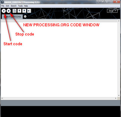 This
section is about the single most difficult problem I faced in
trying to access real world analog data from a purely digital computer.
This
section is about the single most difficult problem I faced in
trying to access real world analog data from a purely digital computer.The essential problem is that the real world is analog and computers are digital (ones and zeros). I found it easy enough at read an analog signal with a simple microprocessor board such as the Arduino Uno board. But it took me some time and a lot of search and study to connect the Arduino output to the input of a digital computer. Of course there are many solutions but I wanted a simple serial out from the Arduino board to a simple serial in to a digital computer. In my case I am using windows 7, with a 64 bit architecture.
The answer came in the form of high level shell programs such as "Processing.org". A close relative of this system is "Wiring" but Wiring required compiling the last tine I checked where Processing will run on a simple code line change and a restart.
As you can see - the processing.org code and code window act very much like the Arduino code window and looks almost the same - which makes the use of this code system a little easier and more comfortable for beginners!
The code listed above in the quick start circuits is for the Arduino Uno processor and produces a serial out data stream but no way to move that serial data into a PC.
My PC Visual C++, object oriented, coding skills are very limited so I used a high level shell type coding systems called "Processing.org". To understand the language and to download it FREE, please visit their site at: http://www.processing.org .
The essence of "processing" is that the code is written in a very simple "C" or BASIC structure but is actually in an object oriented form of JAVA (7.xx). The code can be tested and run quickly in the Processing high level form which has a very high overhead in terms of CPU usage or it can be compiled and used in an executable .EXE form.
A SIMPLE PROCESSING.ORG STUB AS A SAMPLE "PROCESSING" PROGRAM
Here is a very simple "stub" type of program to create a small window on a PC and display any non-NULL serial output sent by the com port 14 from t he Arduino board. Please note that this code is as simple as possible for quick understanding by most readers of this article - but it is not an efficient code. I have used Com14 simply because it is the com port of one of my Arduino boards.
| A NOTE ABOUT THIS CODE Please
keep in mind that this code can be used with any serial device output
that uses a com/USB port as an output. The output of the serial device
can be read, at the input USB port, by any PC and whatever data is
being produced by the serial device or processor can be imported into a
computer. Once the data is inside the computer the data can be
processed, converted, analyzed, charted, and sent to a disk or storage
device and kept as a permanent record. This is a very versatile data bridge from a real world processor or serial data device to a processed computer data record. |
You must have "processing.org" installed to run this example shown below. But the processing user interface is exactly like the Arduino programming interface so the transition is not difficult if you have coded for the Arduino board. Just start processing and enter the program text from below. Then click "Start" and within a few seconds you should see a small black screen called Data Value appear on the PC screen with a series of numbers being read from the serial port. BUT...if the serial value is zero this program as written will not show a number on the screen.
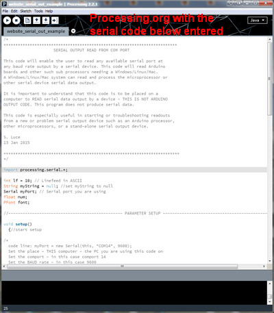 Please
understand this is intended to be a starting point for a project where
you intend to use Arduino data and display it on a PC/MAC/or LINUX
screen. This is just a simple stub and very primitive!!!
Please
understand this is intended to be a starting point for a project where
you intend to use Arduino data and display it on a PC/MAC/or LINUX
screen. This is just a simple stub and very primitive!!!An "else" statement added to the if (myString != null) that prints zero when the string is empty (0) would help this program. And be careful messing with "delay(37)"...for some reason values in delay over 35 or so cause a problem. As this code is written, it may not show a zero value if it looks like a "null" as a string value from the serial port - another enhancement needed.
A Versatile Stub
The interesting thing about this program is that it will read any incoming analog number on a com port (from any processor board such as an Arduino Uno) and display the number on the small screen set up by the program. The baud rate and com port must be set to the appropriate values of your system. I have tested the Arduino program, shown above in the digital volt meter section, to baud rates as high as 115200 and it has performed perfectly.
The program does initially read the incoming data as a string value but converts the string to a float variable called "num".
And keep in mind that the variable "num" is then available to store on disk, to modify by applying any mathematical operations or filters to "num" and "num" can also be plotted on a graph. Each of these operations must be programmed into this stub but the basic problem of moving data from a microprocessor into a PC/MAC/LINUX has been accomplished by this very simple stub.
As you can see in below, this stub is a program to read any data at COM14 out, at a rate of 9600 baud.
Copy the code below this dividing line down to the second dividing line using copy/paste and paste the code directly into a new "Processing.org" code window and click the run arrow. I have tested this code taken directly from this code below and it does work. The comments are in black or red and the code is in blue but the entire text (code, comments, etc.) from the upper line to the lower line should be loaded into a new "processing.org" program window.
This code below acts as a data bridge moving serial out data from the Ardunio Uno board into the PC, then creates a new window on the PC monitor and displays the serail out data from the Arduino in the new PC window. This code must be in the PC and running under "processing.org".
Written by S. Luce/ 15 Jan 2015
/* ************************************************************************************** SERIAL OUTPUT CODE - READ FROM A COM PORT This code will enable the user to read any available serial port at any baud rate output by a serial device. This code acts like a bridge between a serial output device and a computer. This code will read and control Arduino boards and other microprocessors needing Windows/Linux/Mac access.A Windows/Linux/Mac system can read and control the microprocessor or other serial device with a serial data output. It is important to understand that this code is to be placed on a computer to READ serial data output by a device - THIS IS NOT ARDUINO OR MICROPROCESSOR OUTPUT CODE. This program does not produce serial data, IT READS SERIAL OUTPUT DATA. This code is especially useful in starting or troubleshooting readouts from a new or problem serial output device such as an Arduino processor, other microprocessors, or a stand-alone serial output device. Download "processing.org" here: http://www.processing.org S. Luce 13 Jan 2015 ************************************************************************************** */ import processing.serial.*; int lf = 10; // Linefeed in ASCII String myString = null; //set myString to null Serial myPort; // Serial port you are using float num;// float variable called "num PFont font;//default font call //------------------------------------------------ PARAMETER SETUP ------------------------------------------------------- void setup() {//start setup /* code line: myPort = new Serial(this, "COM14", 9600); Set the place - THIS computer - the PC you are using this code on Set the comport - in this case comport 14 - be sure to change this to your com port # Set the BAUD rate - in this case 9600 code line: textSize(40); set the default readout text size to 40 code line: background(0); set the window background color ( ) ... - in this case - 0 for black code line: fill(167,166,222); set the font color ( ) - in this case light blue */ myPort = new Serial(this, "COM14", 9600); //Arduino board at com5, baud=9600 textSize(40); background(0); fill(220,220,255); //light blue font color - 167,166,222 (A7A6DE) size(400,130); // Window size }//end setup //--------------------------------------- END PARAMETER SETUP ------------------------------------------------------- //----------------------------------- START SERIAL READ CODE ----------------------------------------------------- void draw() { /* repeat the program indefinitely */ while (myPort.available() > 0) { /* "myString" is a string value taken from the serial port of the PC/Linux/Mac */ myString = myPort.readStringUntil(lf); textAlign(LEFT); /* get only real values from the port - ignore NULL values */ if (myString != null) { /* background is black */ background(0); /* convert "myString" to a "float" number */ num=float(myString); // Converts and prints float /* print data value as number in the new window */ text(str(num),40,80); /* delay the next reading by 37 milliseconds. If this delay is to small, you may have errors from reading the serial data source to fast. A more complete code would add some kind of "hand shake" maximize speed and efficiency. */ delay(37); }//end if }//end while }//end Draw function //----------------------------------- END SERIAL READ CODE ----------------------------------------------------- |
"Copy" and "Paste" this program as copied from the BLUE (and black font type) text above into a processing "new" program window.
Click the "Run" arrow (>) on the left side of the symbol row of icons on the second line of the processing window shown in yellow in the image below.
Wait a about 10 seconds for a number to appear.
Using this program as is, it will display number in the new program (400 x 30) window, in the window in the default font. The number is the serial output of the Arduino board which is the output of the ADC.
IF YOU WANT TO CHANGE THE FONT
The code above will work - as is. But if you want to change variables such as font type, color, or size follow this set of instructions below:
I have blocked the use of the #48 ACaslonPro-Bold.vlw font because the ACaslonPro-Bold.vlw font must be loaded for the program to use it. The blocked font lines are here:
//font = loadFont("ACaslonPro-Bold"); //font size and color
//textFont(font);
*************************
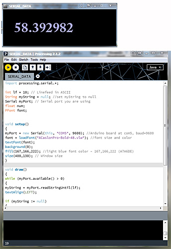
To load the font and see this code work as intended (to the right) the large font must be loaded into your program before the font can be used - just a strange twist of "processing.org" design!
Loading the larger font is very simple:
1. In the top "processing" menu
(File Edit Sketch Tools Help)
2. Select "Tools/Create Font..." and click. You will see a pop up menu window listing hundreds of fonts. For simplicity, use the first font ( ACaslonPro-Bold), near the bottom of the window you will see and a window listing "ACaslonPro-Bold-48".
3. Click the "OK" button and it will be loaded into the program.
4. Remove the "//" in front of both commands and the program will now use the new font. The new lines should look like this:
font = loadFont("ACaslonPro-Bold.vlw"); //font size and color
textFont(font);
5. Restart the program and wait about 10 seconds.
6. The new display is much nicer!
To the right, the upper black window is the output window of this program and the image below is a section of the processing.org program window. This view is with the larger font enabled.
If you try to run without the font loaded, and error message will appear at the bottom of the program window saying font not found.
One last point to remember is that this program will input any serial output in number format. This "processing.org" program is written in a stub form where once the data is inside the PC, in the "SERIAL DATA" program. The variable "num" (the data values themselves) in float format, is available for any purpose including charting, being saved on disk, max and min, etc.
I have tested this program just as I have written it and it does work - but remember to set the com port number to the com port listed on your Arduino board (or other processor) and remember the baud rate is 9600.
...
| MULTIPLE SENSORS AND REMOTE SENSORS |
This subject is on a separate page and a new window will be created. Closing the multiplexing and wireless window will not close this main page.
Click here for the MULTIPLE SENSORS (MULTIPLEXING) AND REMOTE SENSORS (WIRELESS) in a new window
| POWER SUPPLIES |
I am in the process of documenting my new power supply. The supply is untested so it is extremely early for this particular design. I am presently using a design very much like this and it is working well. As untested as this version is - if you are curious...here is the preliminary schematic.
This is an ongoing project to reduce system noise. This is a "work in progress" and is subject to change. Some of the schematics will change day to day. I am in the process of building this power supply as I write this description. Any suggestions especially from the audio people would be greatly appreciated. I am especially interested in low resistance inductors for high frequency noise reduction.
| PARTS |
I buy parts based on quality, cost, and availability. The essential question and problem is how do you obtain first class, original manufacturer, original manufacturer specification, top performance components? As best I can determine now, it is all in where you purchase and how critical the component may be in your circuit. If you are working with the volt meter circuit mentioned in this paper, then buy an LTC2440 ADC and op amp from a top quality, trusted source. OK...where to buy? I will give a list of sources which have done well for me but I will grade them a "A" list, B list and C list.
A few limits to my list. First of all it is a US only source list because I live in the US. I do no have a world-wide list.
MY "A" LIST - TOP OF THE LINE SUPPLIERS
The "A list" are the best manufacturer or source I can find with no regard for price or shipping costs - this is absolute best quality sourcing with quality as the top priority.
Electronics suppliers In alphabetical order...This is my list of top quality suppliers. This is where many US electronics manufactures buy their components. With this type of suppler you can order from one item to 10,000 and more. This type of supplier will back up their products, talk on the phone with you, and ship, usually within hours of receiving an order. These suppliers often carry all variations of a component meaning dip package if it is available, temperature performance grades, etc. These suppliers also have sophisticated data bases from which you choose component grade, temperature spec, noise performance specs, etc. These are often a bit more expensive because they are dedicated to top quality products and because they have massive warehouses, large inventories, and large database selection systems on their website. Sometimes these website can be so complex to find your part, you can spend hours finding exactly the right part - but when it is right - it will do exactly what you want - no surprises!!! And the confidence that the part is right and top quality is very helpful when you are building a prototype circuit. I always buy my critical parts fropm this suppliers.
Although I can not absolutely guarantee the suppliers below are 100 % authentic with every part, I would be astonished if they were not "the real thing"! And if you got a "funny" part, they would exchange it in an instant. If you buy from these people, you are getting the best!
Mouser Electronics This is good and reliable source. When you buy from a source like this you can have confidence in the quality and component choice.
Newark Element14 This is another first class source with a large selection of components.
MY "B" LIST - GOOD PLACES
These sources are generally not of less quality so much as smaller operations. As a result, you may not have the selection of IC temperature performance, or a selection of noise specs. They usually do not have the huge databases and you simply name the component and they list all their data entries for that component. I buy quite often from these sources - these are smaller but solid quality organizations. Please remember this is a US source list. Here is a separate web page listing of mid level and a few high level electronics suppliers:
http://www.instructables.com/community/10-Best-Electronics-Suppliers/
MY "C" LIST - BUYER BEWARE
This is where you "pays your money and takes your chances" - this is the "wild west" of electronics supplies.
You can find the real product such as an LTC2440 but even if it is real, you have no idea where the part came from. It could be a misrepresented manufacturing plant reject - (did not meet manufacturer minimum spec), or a totally fraudulent copy. It can be a discontinued version of the product, or a real working device. You can spend as much time (and money in your time spent) trying to find a good product on EBay as you would if you bought from a high quality supplier, in your own country, in the first place.
There are excellent dealers on EBay but you need to check them out throughly and how do you do that with ICs? I have bought from some very lagitimate sites. I often buy items such as a panel meter where I am just looking for something like a simple $4 meter and I am willing to throw the meter away if it does not perform. I have a pile of meters that do a little of what I expected. As an example, there are almost NO panel meters on EBay that will measure negative voltages - try to find a panel meter that will measure NEGATIVE voltages - even the ads say something like...measures 0 to 20 volts. The ad statement really says measures zero to positive 20 volts - ONLY. And if you wire to meter to - 15 volts, as an example, you will probably destroy the meter. Of all the panel meters ads I have read, not one ad has stated - "WILL NOT MEASURE NEGATIVE VOLTAGES". This all comes from the fact that digital meters work from a 10, 12 or maybe 16 bit ADC and all ADCs work from zero to five volts. There is a special ADC/meter circuit which splits the ADC five volt range into +/- 2.5 volts but it is 50% more expensive.
If you need reliability of a product for a prototype test concept, this is NOT the place to buy. If you get an marginal spec device, how do you know if your concept is marginal or your cheap component is not quite right?
Be VERY careful please - this is a good example of YOU GET WHAT YOU PAY FOR.
| CONTACT ME |
If you find an error in a statement or a schematic, I would be very interested and I will adjust the site if there is an error. Or just write and say hello if you find this website helpful. Thank you for your visit.
The Contact Me page is a new window and will not close this main 2440 website window. My contact me page is here.
| REFERENCE SITES AND PAPERS |
WARNING - Clicking on this link below will actually download the book to your browser in a PDF format but it is a quick download...
Keithley - Low Level Measurements Handbook
Processing.org is the software program I used to make the serial data collection - the jump from the Arduino board to seeing data in the PC. Processing can be downloaded here, FREE:
The processing.org library or reference - this is a list of all of the simple commands available in the language and can be found here:
http://www.processing.org/reference/This is a great outline by Analog Devices engineers on circuit design and layout - especially good on the subject of noise and ground planes.
http://www.analog.com/library/analogdialogue/archives/39-09/layout.pdf
A 32 page paper on ADCs and DACs...good information...good detail
http://www.dspguide.com/CH3.PDF
This is my beginning source info on the use, wiring, and code for the LTC2440, 24 bit ADC:
http://dangerousprototypes.com/forum/viewtopic.php?t=4247&p=42053
Here is the data sheet on the chopper stabilized LTC1052 op amp
http://cds.linear.com/docs/en/datasheet/1052fa.pdf
Here is the data sheet on the LTC2440 ADC
http://cds.linear.com/docs/en/datasheet/2440fd.pdf
A short basic paper on ADCs
http://www.rpi.edu/dept/ecse/rta/LMS/The_ABCs_Of_ADCs.pdf
A small paper on impedance matching of full differential op amps
http://www.ti.com/lit/an/slyt310/slyt310.pdf
A very quick article on impedance issues with op amp inputs:
http://e2e.ti.com/blogs_/archives/b/thesignal/archive/2012/05/30/taming-the-oscillating-op-amp.aspx